
FD3S Rear "Euro" Washer/Fluid Tank
 05-03-18, 01:10 PM
#426
Thank so much.
Nah. It's not even close to over-engineered. It's back to the original-original design (see page one) with the addition of a sump. The horizontal nature of the tank needs it to prevent starvation, it really does. What we're trying to do is make this right, the first time, instead of having a qualifier / work a customer has to do in order to make it function as expected. It will still be 100% OEM fit.
No real estimate. Once we finalize design, we have to print and retest / test fit. After that we'll collect deposits and give production the green light. From there, about 90 days. 
I think its starting to become over engineered. The "low sump" is something people can make themselves if that is needed. Instead of having the pump at the previous suggested point, have a tube that feed a lower res, and have a pump at the bottom. It would not require much effort to make it work. And then the original idea would still work for the rest of us.
If i get parts hanging down from panels its not that attractive solution anymore. The 100% OEM fit was why i wanted it in the first place
If i get parts hanging down from panels its not that attractive solution anymore. The 100% OEM fit was why i wanted it in the first place

The following users liked this post:
ZoomZoom (05-25-18)
05-03-18, 04:06 PM
#429
Matt,
FWIW, the low level sensor light on my Aquamist WI system starts flickering about the time my custom aluminum 1.8 gallon tank is still 1/4 full. IMO, having the sump (and low level sensor) positioned lower in the system would make these nusance "flickers" less likely during hard cornering situations when tank slosh is most likely. Is the plan to position the LL sensor at the lower sump pickup position?
FWIW, the low level sensor light on my Aquamist WI system starts flickering about the time my custom aluminum 1.8 gallon tank is still 1/4 full. IMO, having the sump (and low level sensor) positioned lower in the system would make these nusance "flickers" less likely during hard cornering situations when tank slosh is most likely. Is the plan to position the LL sensor at the lower sump pickup position?
05-07-18, 08:38 AM
#430
Matt,
FWIW, the low level sensor light on my Aquamist WI system starts flickering about the time my custom aluminum 1.8 gallon tank is still 1/4 full. IMO, having the sump (and low level sensor) positioned lower in the system would make these nusance "flickers" less likely during hard cornering situations when tank slosh is most likely. Is the plan to position the LL sensor at the lower sump pickup position?
FWIW, the low level sensor light on my Aquamist WI system starts flickering about the time my custom aluminum 1.8 gallon tank is still 1/4 full. IMO, having the sump (and low level sensor) positioned lower in the system would make these nusance "flickers" less likely during hard cornering situations when tank slosh is most likely. Is the plan to position the LL sensor at the lower sump pickup position?
The feed nozzle will be in the lower sump - as for the LL sensor - that's undetermined. That may stay put depending on size constraints.
05-07-18, 02:14 PM
#431
Yeah. That sounds about right. Not to mention, your tank is baffled extremely well. It's possible during that slosh (depending on where your feed nozzle is) that could potentially be starvation as well.
The feed nozzle will be in the lower sump - as for the LL sensor - that's undetermined. That may stay put depending on size constraints.
The feed nozzle will be in the lower sump - as for the LL sensor - that's undetermined. That may stay put depending on size constraints.
05-08-18, 10:10 AM
#432
Understood, but keep in mind that many systems (Like my Aquamist 2D) disables the pump when the low level sensor is tripped. If it could somehow be positioned in the lower sump area, or midway up the lower sump clocked towards the drivers side, it would totally eliminate this issue. Either way is fine and I'm still committed to purchase, hopefully sooner than later, so don't let my comments cause any additional delay.
The goal is to put the level sensor in the sump. Just gotta figure out where. Feed nozzle will most likely be on the very bottom pointing up.
The initial CAD designs are done. Finalizing these things and I'll post pics.
05-14-18, 10:04 PM
#433
I'm still wondering what the CFD analysis was for? Any images? I can only imagine it being beneficial for baffling design and selecting the ideal pickup location based on the effect of said baffling on simulated fuel slosh...
Any idea as to when you'll be opening an actual group by thread and transitioning out of this interest thread?
Skeese
Any idea as to when you'll be opening an actual group by thread and transitioning out of this interest thread?
Skeese
05-14-18, 10:27 PM
#434
I'm still wondering what the CFD analysis was for? Any images? I can only imagine it being beneficial for baffling design and selecting the ideal pickup location based on the effect of said baffling on simulated fuel slosh...
Any idea as to when you'll be opening an actual group by thread and transitioning out of this interest thread?
Skeese
Any idea as to when you'll be opening an actual group by thread and transitioning out of this interest thread?
Skeese
Actual Group Buy and substantial updates will happen very, very soon.
-M
 05-17-18, 08:54 PM
#436
Ok boys and girls... gather 'round.
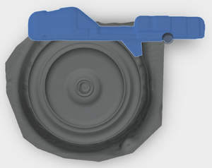
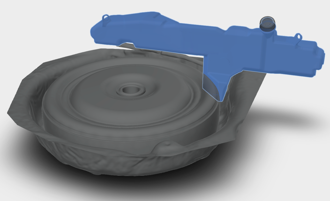
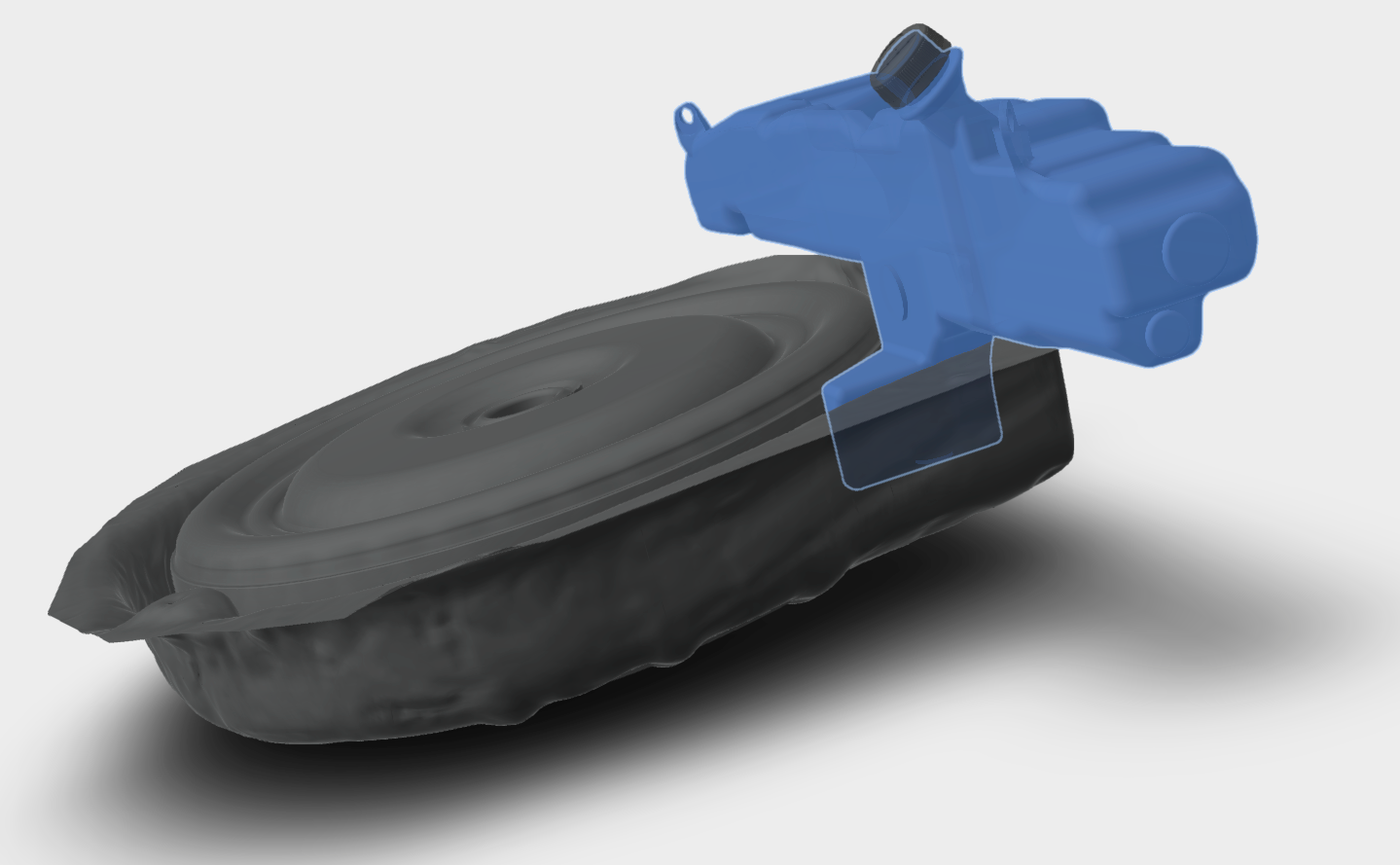
Below if the FINAL (final?) iteration of the Euro tank. The previous designs were great, except for one thing. SLOSH. Under street conditions, it really shouldn't be an issue, but once you start putting some lateral Gs in it, it gets... well. Thirsty.

This is a GIF of the CFD testing on the original design. 75% capacity, 1G *forward* acceleration, for 3 seconds... no real starvation issues.
HOWEVER...
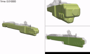
This is a GIF of the CFD testing on the original design. 75% capacity, 1G *lateral* acceleration, for 3 seconds... by 1/2 second, it's starving. The subsequent redesigns didn't do much to help either, so we went with what our gut was originally telling us: a sump.
The question then became, HOW would we do it. We still wanted to maintain the original philosophy; increase capacity, bolt in with no modifications & be "agnostic" to whatever injection kit you run.
So here's what we came up with.


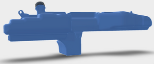
So what are we looking at?
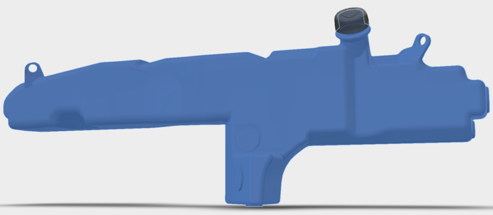
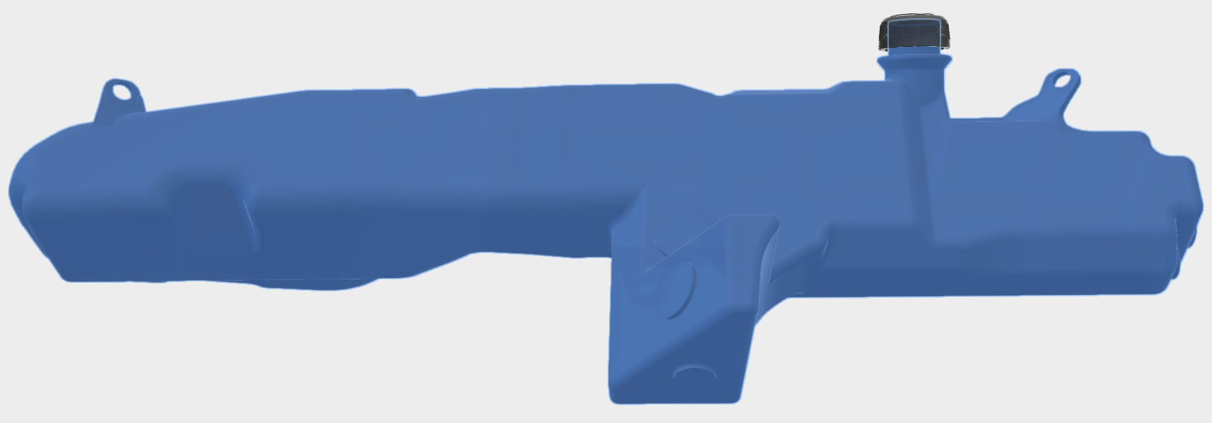
1) Added lower sump to provide a constant reservoir for level sensor / feed nozzle
2) Added boss on the BOTTOM of the sump for optimal nozzle placement
3) Added boss on the side of the sump for optimal level sensor placement (requires spare to be removed)
4) Added boss on the top of the sump for optional level sensor placement (doesn't require spare removal)
...and keep in mind, the original bosses are still there... and really, the bosses are just there as suggestions. The tank material is thick enough that you can really tap it anywhere.
"BUT WAIT!" You may be shouting at your monitor... "I thought that was supposed to fit with all the stock bits in place?".
Well, remember that 3D scanner from last page? Yeah, it has come in handy and looks like it's gonna work.
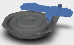

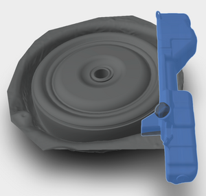
We have 3D prints running right now (it takes a LONG time to print this) and should be able to get it installed and verify what our 3D scanner says about fitment in the next week or so.
Soooo, stay tuned. We'll keep you updated.
Thanks for your support and patience. Spread the word and get those deposits ready!
Below if the FINAL (final?) iteration of the Euro tank. The previous designs were great, except for one thing. SLOSH. Under street conditions, it really shouldn't be an issue, but once you start putting some lateral Gs in it, it gets... well. Thirsty.
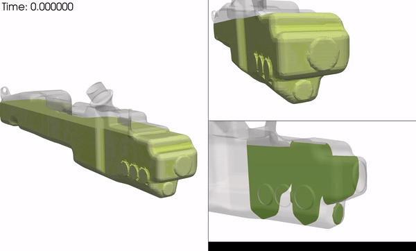
This is a GIF of the CFD testing on the original design. 75% capacity, 1G *forward* acceleration, for 3 seconds... no real starvation issues.
HOWEVER...

This is a GIF of the CFD testing on the original design. 75% capacity, 1G *lateral* acceleration, for 3 seconds... by 1/2 second, it's starving. The subsequent redesigns didn't do much to help either, so we went with what our gut was originally telling us: a sump.
The question then became, HOW would we do it. We still wanted to maintain the original philosophy; increase capacity, bolt in with no modifications & be "agnostic" to whatever injection kit you run.
So here's what we came up with.


So what are we looking at?
1) Added lower sump to provide a constant reservoir for level sensor / feed nozzle
2) Added boss on the BOTTOM of the sump for optimal nozzle placement
3) Added boss on the side of the sump for optimal level sensor placement (requires spare to be removed)
4) Added boss on the top of the sump for optional level sensor placement (doesn't require spare removal)
...and keep in mind, the original bosses are still there... and really, the bosses are just there as suggestions. The tank material is thick enough that you can really tap it anywhere.
"BUT WAIT!" You may be shouting at your monitor... "I thought that was supposed to fit with all the stock bits in place?".
Well, remember that 3D scanner from last page? Yeah, it has come in handy and looks like it's gonna work.


We have 3D prints running right now (it takes a LONG time to print this) and should be able to get it installed and verify what our 3D scanner says about fitment in the next week or so.
Soooo, stay tuned. We'll keep you updated.
Thanks for your support and patience. Spread the word and get those deposits ready!
The following 6 users liked this post by MattGold:
cloud9 (05-18-18),
Jonnybravo408 (05-17-18),
jsemerica (05-19-18),
knotsonice (05-18-18),
MiataRoadster (05-20-18),
and 1 others liked this post.


 05-18-18, 10:00 PM
#447
But here's the real question: how many cars are hitting the track with their spare installed?
05-19-18, 06:16 AM
#448
Originally Posted by 7krayziboi
I don't want to be the pessimist , but is there enough enough space for the 17" spare...or that limits it to S6-S7 model , unless of course it's removed but iunno...
The following users liked this post:
MattGold (05-20-18)