LOG IN
REGISTER
Forums
New Member Section
How to use this Site
Introduce yourself
New Member RX-7 Technical
Website-related Comments, Suggestions and Issues
Vendors Forums
Private Vendor Forums
Vendor Classifieds
Generation Specific
3rd Generation Specific (1993-2002)
2nd Generation Specific (1986-1992)
1st Generation Specific (1979-1985)
Old School and Other Rotary
Tech and Performance
General Rotary Tech Support
Race Car Tech
Single Turbo RX-7's
Rotary Car Performance
V-8 Powered RX-7's
Suspension/Wheels/Tires/Brakes
Engine Management Forum
Interior / Exterior / Audio
Classifieds
The NEW RX7 Marketplace
New/Old Products Review - Non Vendor parts
Regional Forums / Upcoming Events
Rotary Owner Events
NE RX-7 Forum
SE RX-7 Forum
Midwest RX-7 Forum
Mountain RX-7 Forum
South RX-7 Forum
NW RX-7 Forum
West RX-7 Forum
Canadian Forum
European Forum
Australia and New Zealand Forum
Far East Forum
Latin America Forum
General Topics
Racing Kills Lounge
RX-7 Audio/Visual Lounge
Test Area 51
Rotary Archives
Marketplace
Vendor Directory
Become a Vendor
Member Marketplace
Vendor Marketplace
New Posts
Tools
Car Payment Calculator
Tire Rim Calculator
Vin Decoder
Recalls
Technical Service Bulletins (TSBs)
Members List
Live Feed
Gallery
View Dark Mode
Please register or login to enable Dark Mode.
Log In
Register
Threads
Google
Threads
Posts
Advanced
Dark Mode
Please register or login to enable Dark Mode.
Log In
Forgot your Password?
By logging into your account, you agree to our
Terms of Use
and
Privacy Policy
, and to the use of cookies as described therein.
or
Login with Google
Login with Facebook
Recent
Commented
Albums
My Pictures
Gen2n3's Photos
View Profile
Sort:
Commented
Most Recent
Most Comments
Albums
Photos
Hot Wheels FB
0
2019/01/29 21:19:20
Gen2n3
Hot Wheels Mazda 787B (back)
0
2019/01/29 21:03:59
Gen2n3
Hot Wheels Mazda 787B (front)
0
2019/01/29 21:02:55
Gen2n3
Note on BEM Pg S-8
0
2019/01/02 12:54:16
Gen2n3
0
2018/07/24 10:36:57
Gen2n3
0
2018/05/27 21:00:29
Gen2n3
0
2018/05/27 20:59:53
Gen2n3
0
2018/05/27 20:56:25
Gen2n3
0
2018/05/15 17:50:04
Gen2n3
0
2018/05/09 12:24:09
Gen2n3
0
2018/05/09 12:24:09
Gen2n3
0
2018/05/08 18:59:08
Gen2n3
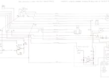
Flex Print Schematic
0
2018/05/08 14:22:45
Gen2n3
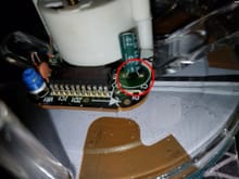
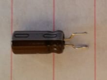
I suspect this capacitor, C1, was previously replaced. What are the values stamped on the capacitor? It should be 1uF @ 50V.
0
2018/03/18 19:06:44
Gen2n3
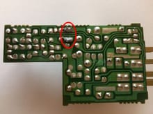
These solder joints are new when compared to the rest on the board. The components above were replaced before.
0
2018/02/01 21:07:29
Gen2n3
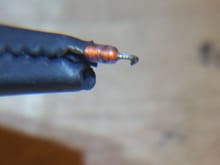
It doesn't take long to put each 45* bend in each lead.
0
2017/03/21 13:32:54
Gen2n3
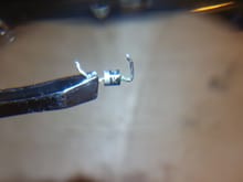
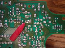
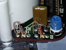
Red cap points to the solder joint of ZD4. Note its separation from ZD5 and ZD7's solder joints. It is normal for the solder joints of ZD5 & ZD7 to touch. They share the same electrical connection.
0
2017/03/21 08:11:12
Gen2n3
Here is C3 soldered back in place. I ensured solder was on the top side as well. This remove and reinstall did not fix the odometer.
0
2017/03/17 13:18:45
Gen2n3
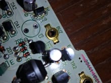
C3 removed. The negative lead hole (on the left) looks a bit tarnished from the original cap leaking.
0
2017/03/17 13:18:43
Gen2n3
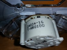
Tachometer motor
0
2017/03/17 08:13:14
Gen2n3
C1 is a 1uF, 50V capacitor.
0
2017/03/17 08:13:13
Gen2n3
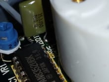
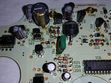
VR1 and C5
0
2017/03/17 08:13:12
Gen2n3
IC1 shown here.
0
2017/03/17 08:13:11
Gen2n3
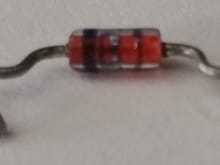
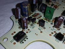
Diodes D2(J3) and D3 need additional info on part numbers.
0
2017/03/17 08:13:09
Gen2n3
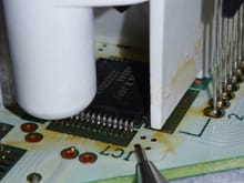
Mechanical Pencil points at IC7. IC7 is underneath the Odometer Digital Display.
0
2017/03/16 15:37:51
Gen2n3
Mechanical Pencil points at IC2.
0
2017/03/16 15:37:49
Gen2n3
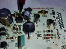
The HUGE Zener diode is ZD6. It's P/N is either 3NB PZ627, PZ627 3NB, or just PZ627.
0
2017/03/16 13:31:59
Gen2n3
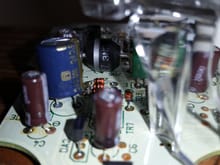
Different angle of C3 and surrounding components.
0
2017/03/16 13:31:54
Gen2n3
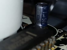
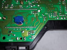
C3 was previously replaced with this blue Panasonic capacitor.
0
2017/03/16 13:31:52
Gen2n3
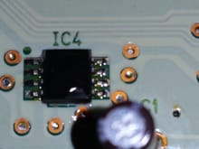
IC4 P/N*: (Stamped Texas Instruments) Line 1: 12903 Line 2: 1ABA (last A is boxed).
0
2017/03/16 13:25:56
Gen2n3
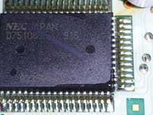
IC5 P/N: Line 1: D75108GF(A) 915 Line 2: NEC Japan Line 3: 9235PX702
0
2017/03/16 13:25:55
Gen2n3
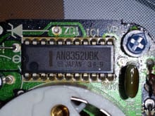
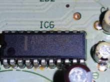
IC6 P/N: Line 1: AN8363UBK Line 2: Japan 41.2
0
2017/03/16 13:25:52
Gen2n3
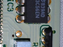
IC3 P/N: B39AD 93C56EN
0
2017/03/16 13:20:32
Gen2n3
IC1 P/N*: (Stamped Motorola) 74HC14A 343BW
0
2017/03/16 13:20:31
Gen2n3
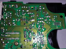
Top 1/3 of circuit board backside.
0
2017/03/16 13:17:52
Gen2n3
Middle 1/3 of circuit board backside.
0
2017/03/16 13:17:50
Gen2n3
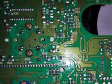
Bottom 1/3 of circuit board backside. Note the surface mounted components.
0
2017/03/16 13:17:48
Gen2n3
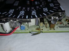
Side view of speedometer with VR (blue Phillips head). VR is the speedometer adjustment potentiometer.
0
2017/03/16 13:15:50
Gen2n3
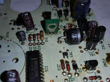
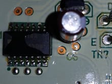
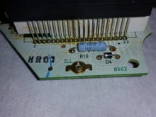
R10 is a 200Ω resistor D4 is a diode with no legible markings.
0
2017/03/16 13:15:48
Gen2n3
0
2017/03/16 12:42:43
Gen2n3
First
Page
4 of 6
Last
Go To
Page
1
2
3
4
5
6
4 of 6
Go To
GO
Go to page
of 6
pages
1
2
3
4
5
6