
Write-Up - MR2 Electrical Power Steering Conversion

Write-Up - MR2 Electrical Power Steering Conversion
Well I thought some other people might be interested in this conversion. I will say now that you do not get any performance gain out of this. I did it for the reason that when I bought my car it had a pulley kit that I preferred to leave on and the stock power steering system had been removed. Rather than change the pulleys on the alternator, clutch fan and crank I was able to source a MR2 pump for $100 shipped from a buddy in Colorado (thanks Chance "SlideAlliance").
I first began with having a bracket made for the pump. My buddy Martin at Parts Shop MAX USA was able to make it in 20-30 minutes. What we did was used the stock power steering bracket holes on that block as the mounting point. Here's a quick look on how we did it.
Sorry for the quality of these pictures. They were taken with my iPhone.
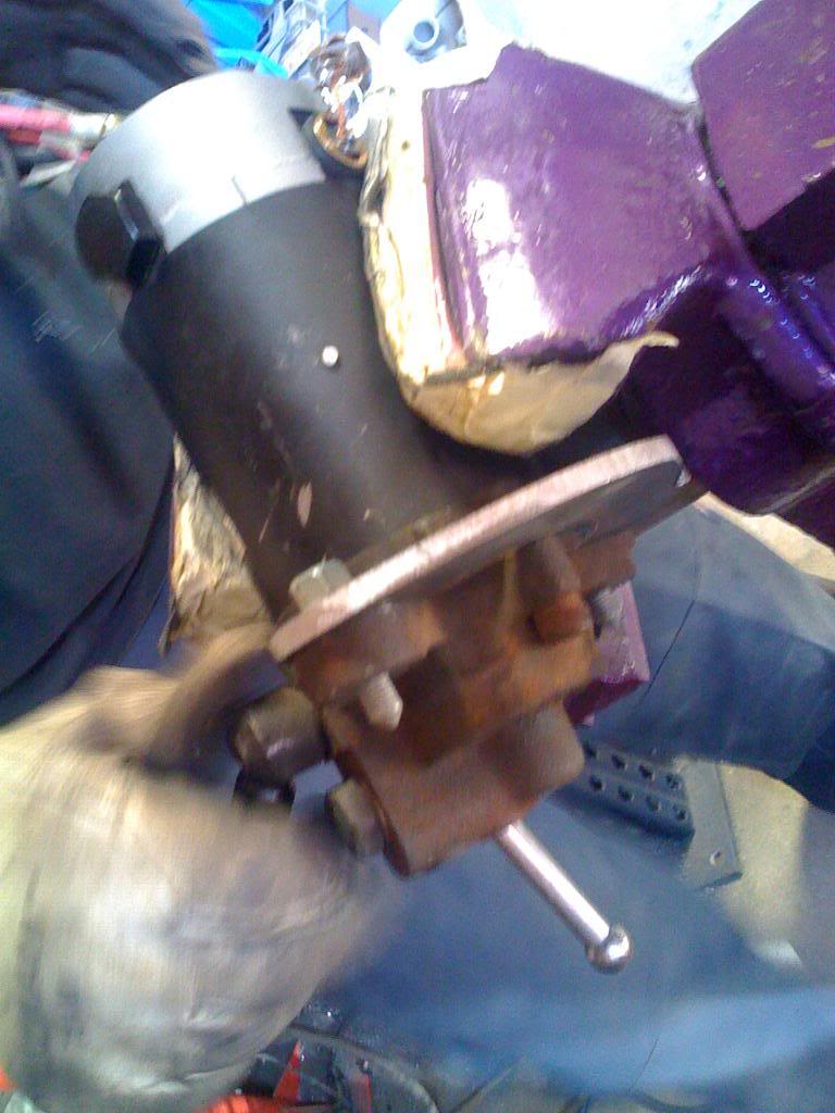
The start of the bracket
Here he made a C shaped bracket that utilizes both of the pumps mounting holes
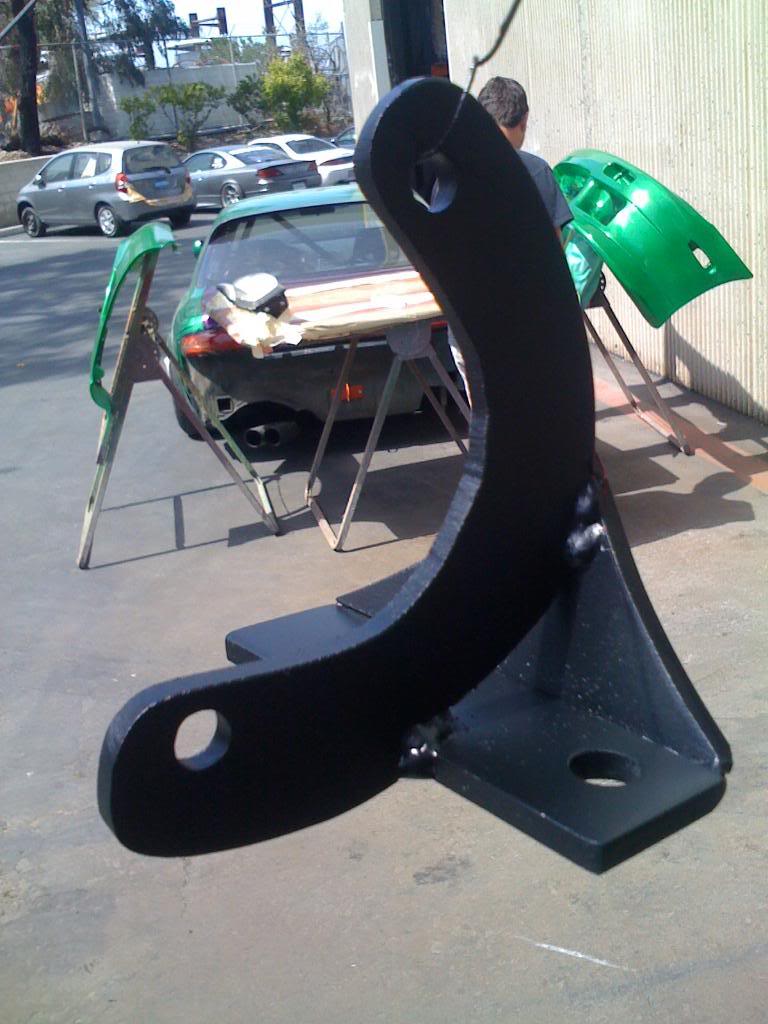
Here's the final bracket after both parts were welded together and painted
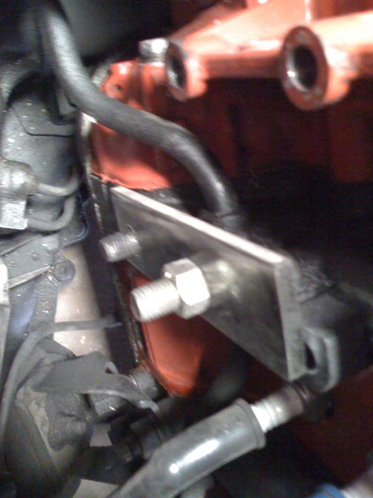
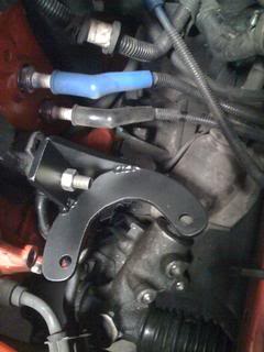
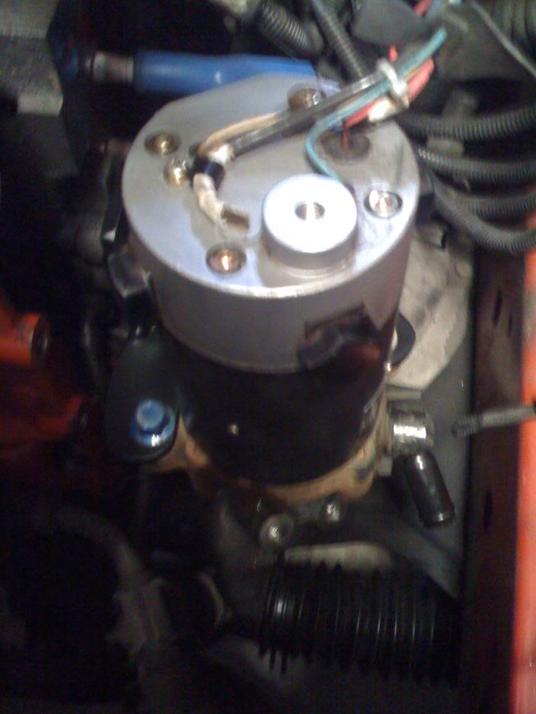
Mounted Bracket, Then mounted the pumps (we threaded the holes in the bracket)
I first began with having a bracket made for the pump. My buddy Martin at Parts Shop MAX USA was able to make it in 20-30 minutes. What we did was used the stock power steering bracket holes on that block as the mounting point. Here's a quick look on how we did it.
Sorry for the quality of these pictures. They were taken with my iPhone.
The start of the bracket
Here he made a C shaped bracket that utilizes both of the pumps mounting holes
Here's the final bracket after both parts were welded together and painted
Mounted Bracket, Then mounted the pumps (we threaded the holes in the bracket)
Part 2 - Plumbing
Now we get into the plumbing.
I went with Earls fittings for this. I ran 2 fittings off the rack of course. I can't remember the sizing and need to find the paper I wrote them down on so ill post those later. I used a 90 degree high pressure fitting off of the pump, used 2 feet of high pressure line and ended it with a 45 degree high pressure fitting that goes onto the inlet of the rack. I was able to use one of the my brothers spare P/S reservoir from his old civic that we had lying around. It was fairly straight forward from there.
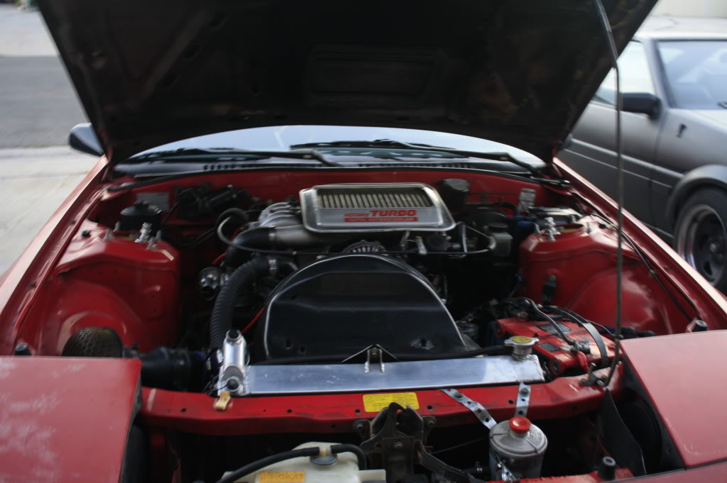
I mounted the reservoir up in the front of the car for now. This is a temporary location until I can fund a new P/S cooler. For obvious reasons I ran the reservoir so far away so that i can extend the lines as far as possible to act as its own cooler. From the pump itself I went to Kragen and found a nice 4 foot hose that luckily fit right over the pumps suction nipple. That hose I routed through a hole I found underneath the battery tray that led to the front area. I will have to snap some photos of that tomorrow. Next thing was the return from the rack that goes to the top of the reservoir. This hose you can route with the other one coming from the reservoir. In regard to the fact that this model utilized the steering sensor. I just capped of that hole with a bolt and some sealant. I plan on running a T in the high pressure line with a hose running to the capped hole in the future.
Here you can see where I mounted the reservoir.
I went with Earls fittings for this. I ran 2 fittings off the rack of course. I can't remember the sizing and need to find the paper I wrote them down on so ill post those later. I used a 90 degree high pressure fitting off of the pump, used 2 feet of high pressure line and ended it with a 45 degree high pressure fitting that goes onto the inlet of the rack. I was able to use one of the my brothers spare P/S reservoir from his old civic that we had lying around. It was fairly straight forward from there.
I mounted the reservoir up in the front of the car for now. This is a temporary location until I can fund a new P/S cooler. For obvious reasons I ran the reservoir so far away so that i can extend the lines as far as possible to act as its own cooler. From the pump itself I went to Kragen and found a nice 4 foot hose that luckily fit right over the pumps suction nipple. That hose I routed through a hole I found underneath the battery tray that led to the front area. I will have to snap some photos of that tomorrow. Next thing was the return from the rack that goes to the top of the reservoir. This hose you can route with the other one coming from the reservoir. In regard to the fact that this model utilized the steering sensor. I just capped of that hole with a bolt and some sealant. I plan on running a T in the high pressure line with a hose running to the capped hole in the future.
Here you can see where I mounted the reservoir.

Continued - Wiring
This is the tricky area of doing this. Now the pump has two plugs that the stock MR2 uses. One plug has 2 wires that are the power and the ground. The other is one you can dispose of. Its the MR2's version of the steering sensor mechanism.
Now utilizing the power and ground cable off of the pump, I decided I wanted to run the pump to a switch rather than running it to a ignition source. This was to prevent any issues while cranking the car.
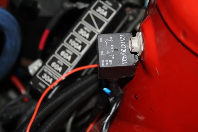
I am definitely no wiring guru, but was able to figure this out with simple googling and what not. I used a 12VDC 30/40a relay. It's a 5 prong relay but you will only need 4 of the 5 prongs. The relay is labeled by number. 30, 85, 86, 87 and 87a
Here's a simple breakdown of the wiring to the relay
Pump Power Cable - 30
Wire to Switch - 86
Battery Power Cable - 87 and 85 (explain further along in the write up)
In regards to the switch and battery power cables.
First off the battery wiring. It's fairly simple
Run a wire (I used a 10 gauge) to the #85 Prong, Now using a T-Tap run another wire to the 87 prong. Done with that
Switch wiring. Super simple and easy.
Run a wire from the 86 prong to the 1 of the prongs on the switch. Now from the other prong on the switch, run a wire and ground it. Switch complete. This you can mount anywhere. I mounted it near the armrest next to the factory security light.
Pictures of the relay wiring and mounting
Now last but not least you just need to ground the black wire off of the pump a good clean ground on the chassis and your set. Fill the lines and reservoir and your golden.
Now utilizing the power and ground cable off of the pump, I decided I wanted to run the pump to a switch rather than running it to a ignition source. This was to prevent any issues while cranking the car.
I am definitely no wiring guru, but was able to figure this out with simple googling and what not. I used a 12VDC 30/40a relay. It's a 5 prong relay but you will only need 4 of the 5 prongs. The relay is labeled by number. 30, 85, 86, 87 and 87a
Here's a simple breakdown of the wiring to the relay
Pump Power Cable - 30
Wire to Switch - 86
Battery Power Cable - 87 and 85 (explain further along in the write up)
In regards to the switch and battery power cables.
First off the battery wiring. It's fairly simple
Run a wire (I used a 10 gauge) to the #85 Prong, Now using a T-Tap run another wire to the 87 prong. Done with that
Switch wiring. Super simple and easy.
Run a wire from the 86 prong to the 1 of the prongs on the switch. Now from the other prong on the switch, run a wire and ground it. Switch complete. This you can mount anywhere. I mounted it near the armrest next to the factory security light.
Pictures of the relay wiring and mounting
Now last but not least you just need to ground the black wire off of the pump a good clean ground on the chassis and your set. Fill the lines and reservoir and your golden.
My final thoughts on the outcome.
Well a buddy of mine works for autozone so I used their alternator tester. The one you use while the cars running. Well the sad part is my alternator is slowly going out only putting out 59 amps at idle. This was with the pump, radio and lights off. We did the test again and surely enough with just the pump on the alternator was still putting out 58.6. So the affect on the alternator, even a bad one, wasn't much.
As for the feel of it, it feels almost like a newer cars P/S. In my old car I could feel the difference on a mechanically driven pump while turning parked. With this it feels thoroughly consistent through a full turn lock-lock. The steering was fairly too light for my liking at first but I have adjusted to it.
Total I spent came out to around $200
Not many people may see a need for this in any way, however I thought for those who might be interested that this would be helpful.
Thank You

Trending Topics
thanks kent, another good thing is you don't have to route intercooler piping around the stock pump or anything. and this could also be done to any car, in reality the wiring is no different along with plumbing, it would just be your choice of location and what not.
Some one should think about producing the mounting kits. I think its a great alternative for people who run FMIC without worries about the PS pulley hitting the IC piping, or needing to remove the PS in general. Sorry I sound stupid right now, I only had 3 hours of sleep.
Joined: Feb 2001
Posts: 29,798
Likes: 128
From: London, Ontario, Canada
That's really cool. However....
Your test at AutoZone was flawed. This pump is often used in the EV community to power up steering systems as opposed to belting the pump off of the electric motor (which is not turning at "idle" and thus will offer no steering assist). While the current draw of the pump is fairly low at idle (only a few amps), turn the wheels lock to lock and you will see the real story. This pump pulls about 35A at full song.
I didn't see any mention of a fuse in your writeup.
T-taps (vampire clips) become intermittant after about a year.
The battery has nothing to do with it.
My final thoughts on the outcome.
Well a buddy of mine works for autozone so I used their alternator tester. The one you use while the cars running. Well the sad part is my alternator is slowly going out only putting out 59 amps at idle. This was with the pump, radio and lights off. We did the test again and surely enough with just the pump on the alternator was still putting out 58.6. So the affect on the alternator, even a bad one, wasn't much.
Well a buddy of mine works for autozone so I used their alternator tester. The one you use while the cars running. Well the sad part is my alternator is slowly going out only putting out 59 amps at idle. This was with the pump, radio and lights off. We did the test again and surely enough with just the pump on the alternator was still putting out 58.6. So the affect on the alternator, even a bad one, wasn't much.
I didn't see any mention of a fuse in your writeup.
T-taps (vampire clips) become intermittant after about a year.
The battery has nothing to do with it.
506 RWHP 12A..
Joined: May 2004
Posts: 485
Likes: 3
From: Norway
I have a similar setup in my FB, but im using a Opel Astra (european model) pump, fitted behind the drivers seat for better weight distribution. What i learned:
- Aaron Cake is definetivly right. My pump draws about just below 30 amps when turning.
- The setup (well the FB steering box) requires about 70 bars of line pressure to function properly.. Im not sure i would be comfortable with running anything other than professionally made hydraulic hoses. Remember the oil can get hot, and it is under high pressure.
- Im using the pumps speed sensor wire to slow it down when driving. It makes the steering light at slow speeds, but firm at the track.
Other than that, im loving my setup. I moved about 15 punds lower to the ground, and more centered.
Any more info as to how this works? I seem to remember these using a PWM signal to manage the pump speed. How did yours work? Is it a gradual increase or do you have it on a toggle?
thanks much.
well i cant edit my original posting. But since then ive redone the wiring setup to the pump. its alot more reliable and makes me more comfortable with driving it.
I went ahead and trashed the old wiring setup and went with a 100a circuit breaker and a Hi Amp relay. also changed the power and ground wires to the pump to 10 gauge wiring. soldered and shrink wrapped. currently still running off a switch so I can shut it off whenever its not needed. mostly freeway.
I found a guy who did the same setup on his jeep and he made a nice little diagram to go off of. ill post pics when there's better light outside.
heres the diagram

Enjoy
I went ahead and trashed the old wiring setup and went with a 100a circuit breaker and a Hi Amp relay. also changed the power and ground wires to the pump to 10 gauge wiring. soldered and shrink wrapped. currently still running off a switch so I can shut it off whenever its not needed. mostly freeway.
I found a guy who did the same setup on his jeep and he made a nice little diagram to go off of. ill post pics when there's better light outside.
heres the diagram
Enjoy

I'm sorry I mis-wrote my question. In the OPs description it sounds like he doesn't run lines to the control valve in the steering system. It sounds like he just ran lines straight to the steering rack. If this is how it was done how does the system know which way you are steering?

In the factory diagram you can see lines going to and through the valve and then to the rack.
In the factory diagram you can see lines going to and through the valve and then to the rack.
When he said "that goes onto the inlet of the rack" he meant the inlet of the control valve. Since all of the plumbing ins/outs are right there at the valve, and the valve is cast into the same body as the rack I think it is just semantics. Otherwise, you are right.. it would be power one way steering all of the time.
I'm sorry I mis-wrote my question. In the OPs description it sounds like he doesn't run lines to the control valve in the steering system. It sounds like he just ran lines straight to the steering rack. If this is how it was done how does the system know which way you are steering?
In the factory diagram you can see lines going to and through the valve and then to the rack.
In the factory diagram you can see lines going to and through the valve and then to the rack.
Rotary Enthusiast


Joined: Aug 2004
Posts: 1,326
Likes: 9
From: Australia - Perth
in addition it would be nice it the OP came on and let us know how he got on.
Im in the process of doing this as well, but a bit differently.. I dont want the system running 100% of the time (and I dont want a on off switch either)
Im in the process of doing this as well, but a bit differently.. I dont want the system running 100% of the time (and I dont want a on off switch either)

Does the FC has a speed sensor?