1985 GSL OEM Audio Full Modernization Upgrade
#1
Junior Member
Thread Starter
1985 GSL OEM Audio Full Modernization Upgrade
Car: 1985 GSL Currently fully stock interior and stereo, tuner, cassette and eq.
Goal: Instead of fitting (barely) some version of a double din stereo into the factory slot, both tainting the factory lines and aesthetic. I decided to put my years of being an electronics technician to work for me. My task was to test, diagnose, poke, prod, learn and document the workings of the Mazda Clarion audio system to see if an upgrade was possible, namely Bluetooth and/or iPod integration.
Result: I found the audio system very well engineered for just the project. Clarion had made the stereo system with all audio and power signals EXTERNAL between components, perfect for analysis and for hijacking signals.
The inspection: First I needed to locate and learn the path of signals, both audio and power/ground. This task allowed me to learn the entire system and have a very solid foundation to build on.
The Clarion works in this fashion:
1 The cassette deck is the master in charge of the system, main power for the audio system enters through the cassette deck and is distributed from there.
2 The tuner gets powered by the cassette deck, as well as the EQ.
3 The audio path is as follows: Audio is created in the tuner, it travels out the DIN cable to the EQ, the EQ sends the audio to the cassette deck, the cassette deck sends the audio to the EQ where it is equalized (given the EQ is powered on), the audio leaves the EQ and returns to the tuner where it only goes to the volume ****, the varied audio leaves the audio **** and exits on the 5 pin DIN to the balance joystick and on to the amplifiers.
4 When a cassette is installed, the cassette deck drops the 12v line that powers the tuner, thus ensuring that there is only one audio signal going to the EQ and the volume ****. If you leave 12v on the tuner when a cassette is in, both the tuner audio and the cassette audio will play simultaneously, this is why the cassette deck is in control.
I learned that inside the 8 pin audio DIN, there is a 12v line. This line is to ensure the EQ and amplifier get the "ON" signal when either the tuner is turned on, or a cassette is inserted, this fact is important, I'll expand later.
Now I had a complete understanding of the signal and audio path, and I began testing and experimenting. First I plugged a cable into the headphone jack of my ipod, I frayed the other ends exposing the conductors. I then dug out an old Gen2 cassette deck for testing purposes. I left the cassette deck DIN whole but just peeled back and exposed the wires so that I could "piggyback" the signal lines. I then connected the ipod to the audio "IN" lines that would be coming from the cassette deck to the volume ****. I inserted a cassette tape and it worked! I had audio, but I also had warbled sound from the cassette deck as well, because under normal conditions the cassette deck disables the tuner ensuring only one audio signal goes to the volume ****. It was then that I cut the DIN alltogether to try and isolate the audio. This is when I learned the importance of the fabled 12v signal that rides the DIN cable and ensures the amplifier turns on. So....I touched a 12v test lead to the 12v line in the DIN cable and it worked right! I had ipod audio, volume control, and the tuner was off.
Now I needed to engineer exactly what I wanted to do which was this:
I decided to build a small electronics project box to house components, the key here was to have my box be inbetween the DIN cable that is coming from the EQ to the volume ****, as well as intercept the 12v signal that the cassette deck feeds the tuner in "non cassette" mode. My project would need to fill the following requirements: First, the 12v signal that controls the tuner from the cassette deck would need to be under my control; second the audio would need to be switchable from bluetooth to ipod to keep from playing over one another; third, the factory audio system would have to remain unmodified both internally and visually, to keep the 1985 aesthetic.
Lets begin:
I started with a 5 pin relay that flops between normally open and normally closed from a common source. This would give me the 12v to the tuner for normal operation, and when I energized the relay, would take away the 12v signal from the tuner, simulating a cassette insertion. I then chose a pushbutton latching switch to energize the relay, and a triple pole double throw toggle switch to effectively swap between the audio from the bluetooth and the ipod. I then picked up a USB powered bluetooth controller and a hardwired USB power source. Unknown to me until this project, iPods can use different voltages to charge them. 5v USB and 12v. I sourced an ipod cable from an old pioneer ipod controller, mapped the pins and researched the pinout. After locating the 12v wires for the ipod I added a connection block next to my relay to distrubute power, and one opposite, to distribute the ipod audio respectively. Now, the relay at rest will naturally send the 12v normal operation line from the cassette deck, straight to the tuner, however when I energize the relay, I will not only kill the tuner, I will also have switched 12v power for my USB power supply as well as my ipod charging.
Now with a good design for the box, I started on the ash tray and the switches. I sourced some fine plastic from an old SkiDoo Mach1 airbox, some of the best plastic I've ever used for fabricating, it cuts well, is flexible but rigid, holds its shape, and is very durable. I trimmed the metal release latch on the ash tray to allow for insertion of the fabricated plastic panel. I then dremeled out the ridges in the ash tray to make a nice tight pinch point for the bottom of the panel. I decided to use countersunk screws on the top, for clearance purposes when the ash tray closes, so I used an old PC power supply for screws and matching threaded holes in easy-to-work-with metal. I cut the metal into small strips and bent them just beyond 90 degrees to hold the top of the panel. After trimming the panel, I drilled the holes and mounted the switches. Next I test fit the cable and trimmed a slot for the cable to pivot in.
Now to wire the switches to the box. Lets not forget what we need for electrical connections: 12v to the switch, 12v from the switch, ground to the switch for the LED. 9 audio wires, 3 ipod to switch, 3 bluetooth to switch, 3 out from switch to the DIN cable. I decided that the best cable for the job was a VGA extension cable with male one end and female the other. VGA cables as we all know are extremely tough and carry 15 pins. I searched and found that 28 gauge wire can take lots of current at less than 3 feet length, I was working with around 14 inches of cable so I wasn't worried at all. I tested the relay for activation current and measured that the relay energized and consumed .13 amps. I was good. Not to mention that the VGA cable would connect halfway so in the event that I needed to remove the audio system for repairs, I could unplug the ash tray VGA from the stereo and remove it, rather than have hard wired connections everywhere.
Now to build the box:
The box will have one cable that connects to the vehicle 3 pin harness that originally went to the tuner, and one cable that connects to the tuner. Remember we are only hijacking the 12v "on" signal from the cassette deck and the other two wires were connected together in the box to pass straight through. One large VGA going to the ash tray switch panel; two DIN cables, one to the tuner, one to the EQ; the ipod cable; the bluetooth audio input; and a ground for the box itself. Inside the box are the relay, two distribution blocks, and all the remaining cables to be connected in some way.
My first test after building the box had some terrible audio feedback from the bluetooth with the charger powered on, so I added a ground loop isolator on the final feed from the toggle switch to the DIN cable input. This ensured that if there was ground loop noise on either the bluetooth or the ipod, the isolator was after both of them and would work either way.
The trick: Remember the 12v signal in the DIN cable that energizes the amplifier? So this part was tricky but it got resolved. Under normal operating conditions the 12v line in the DIN is active. But, when you kill the tuner and you DO NOT have the cassette player operating, the cassette player does not provide the 12v signal in the DIN, and the amplifiers stays off. So the first thing I did was connect the 12v din signal to the Normally Open side of my relay, you know, the side that gets the switched power that turns on the ipod charging and the Bluetooth power supply. That worked well until I turned off the relay, then the normal operation of the stereo system was to provide 12v on that line, which back-fed and powered the ipod and Bluetooth. I solved this with a diode between the DIN 12v line and the switched 12v side of the relay. This allowed the 12v from the relay to pass to the DIN when the relay was energized, but the 12v from the DIN could not pass back to the switched side of the relay when the stereo was normally operating.
Install:
The first thing I did was install the bluetooth controller in my glovebox, it came with a small metal clip to hang from clothing when you want to use it as handsfree calling etc. I installed the metal clip to the inside of the glovebox, as a safe place to hang the controller when not in use for voice. It also came with a plastic circle with metal interior for magnetically mounting on a surface, I installed the circle on my dash just left of the glovebox door, so in the event I want handsfree calling, I just take it from the storage clip in the glovebox and magnetically attach it to the dash. Next I placed the box behind my stereo in front of the HVAC plenum. I connected everything and weaseled the stereo back into the dash. Next I threaded the ash tray VGA to the passenger side of the stereo mounting steel and it fit nicely. The rest was trim screws and pugging in the bluetooth controller, securing the cables up with zip ties under the dash, and tucking the ipod cable under the shifter console popping out next to the passenger seat. The other good thing was the USB charger had two connectors so I let the unused one hand out a couple inches on the transmission tunnel on the passenger side. In today's world you can never have too many free USB charging ports.
The result:
All I can say is WOW!!! I hadn't realized how badly degraded my tuner had gotten in 32 years. Just a couple weeks ago the shoddy FM transmitter I was using barely got me the audio I wanted, most times I would have the volume at 75% or more at 55 with the windows down. Now the sound is pure, crystalline clear, and LOUD. I had misjudged my 25WX2 amps behind the seat. With the volume at 25% its a very good driving volume. I tested some loud metal at about 65 windows down and 50% volume was more than adequate. I was shrouded in music and didnt have wind noise or my failing muffler.
Now, when approaching my car, the dash and stereo look and act stock, however when you open the ash tray, the switches are the only tell. I have full powered ipod integration or switch to bluetooth, for streaming audio, calls, navigation and whatever your device can throw at it. The best part is the stereo is 100% unaltered, all signal modification takes place outside the stereo in my box, and everything is connected with proper connectors, you can unplug the box at any time and the stereo will be back to normal. I'm going to post this and then add images, so not to ruin the encyclopedia I've just typed lol.
#2
Junior Member
Thread Starter
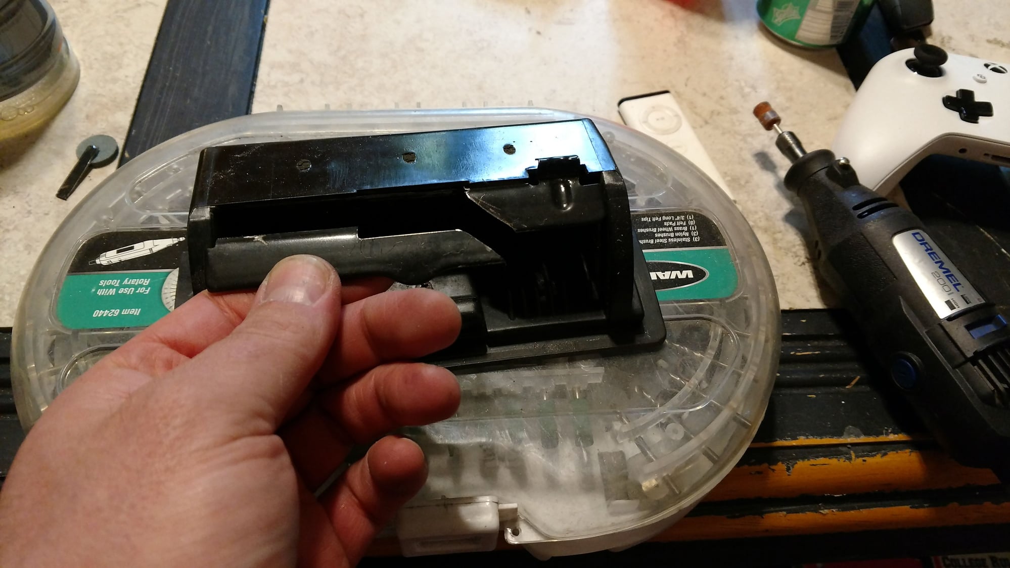
Initially trimmed the metal locking bar from the ash tray.
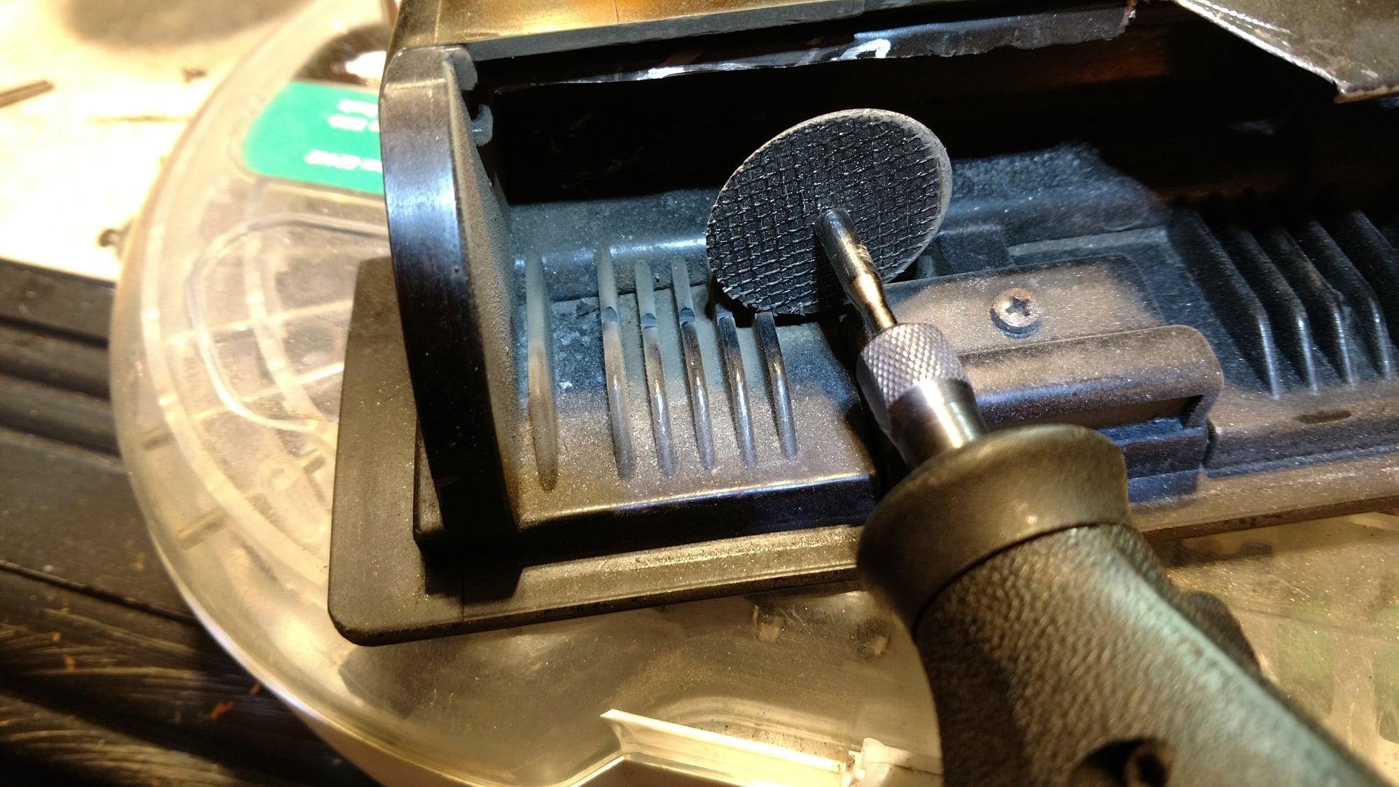
Cut the groove in the ashtray to house the plastic switch panel
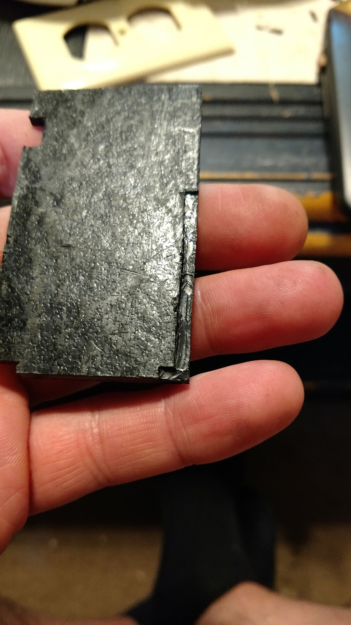
Plastic panel to house the switches, trimmed to sit flush in the ash tray

Ahhh, a perfect fit.
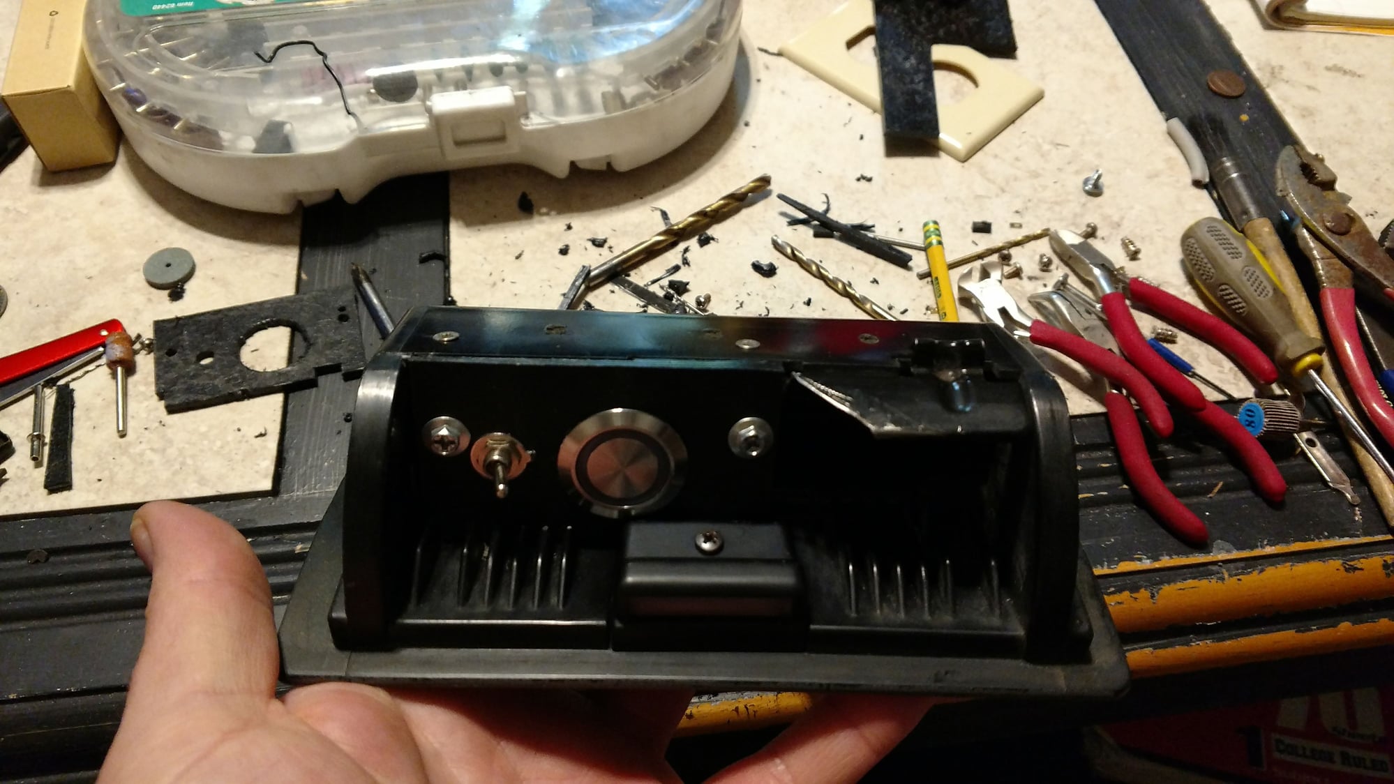
This is the panel all mounted, notice the countersunk screws in the top due to the minimal clearance when the ash tray is flipped in.
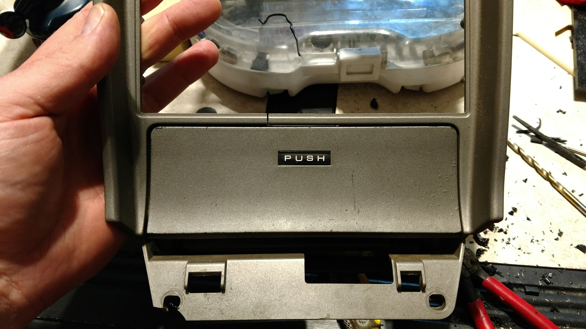
Fully closed with switch panel installed.
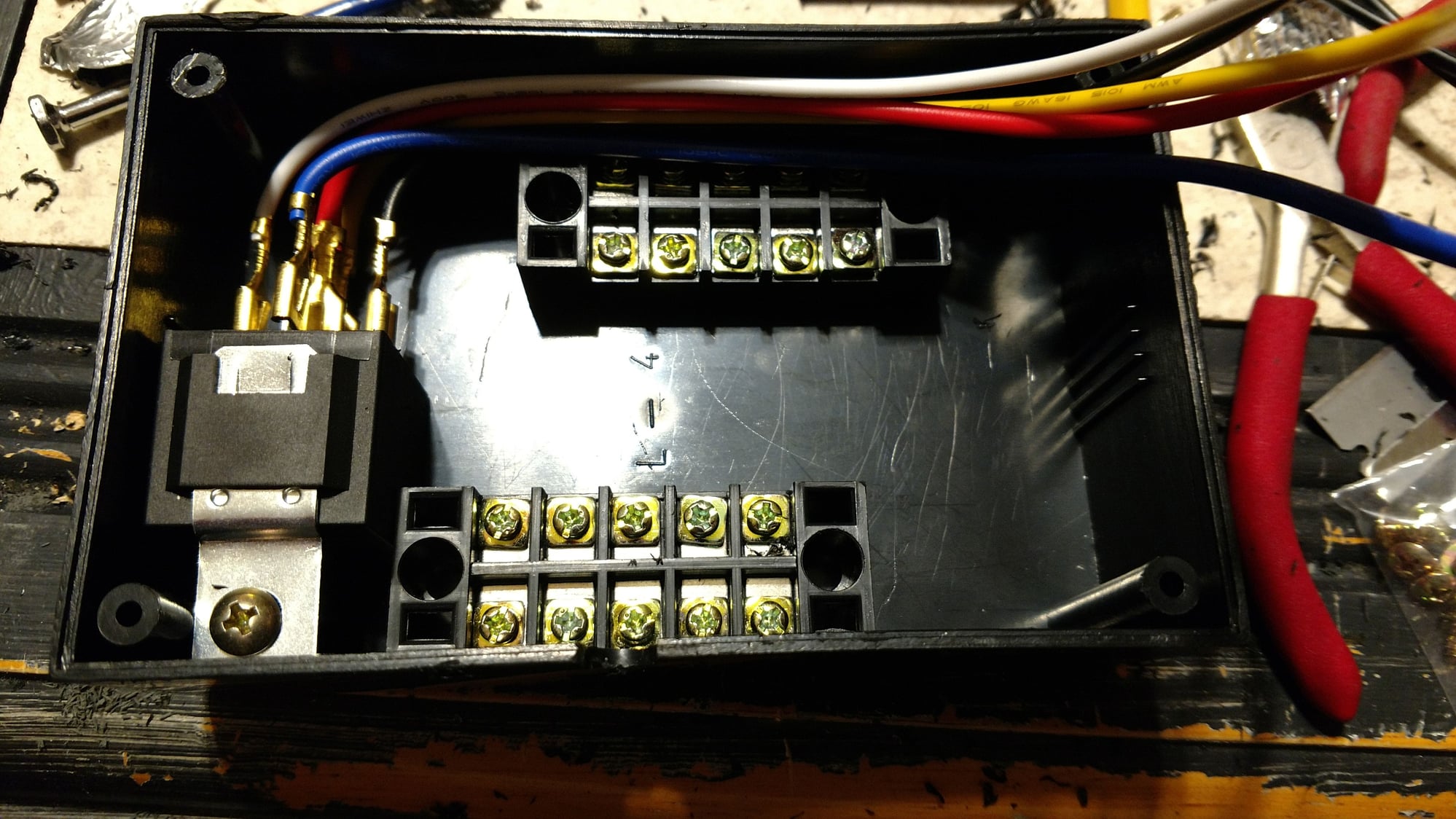
Box beginning. Relay on the left, relay distribution block top, ipod audio and power block down bottom, the ipod cable hole has been cut near the center screw of the box's side wall.
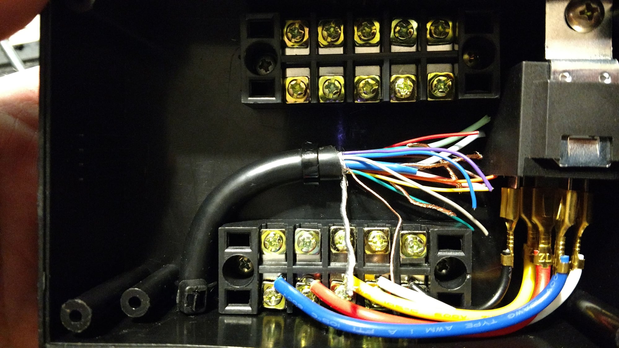
VGA cable from the ash tray switch panel in place, relay connected to the distribution block
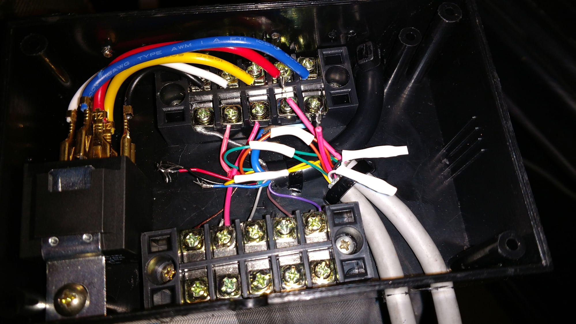
Preliminary connections between the black VGA to switch, and the two gray DIN cables to and from the stereo
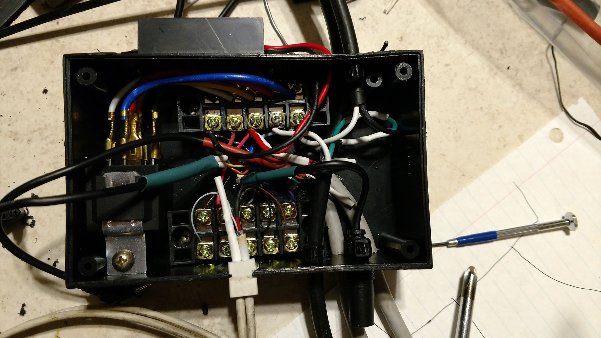
USB charger mounted up top and wired to the relay power block, bluetooth audio female connector bottom right between the gray VGA cables, the black cables that house the black, white and green wires are the cables to and from the car harness 3 wire plug and the tuner. The two cables hanging out the left side are the final audio cables, from the VGA switch cable, and to the DIN cable, they are 3.5mm audio jacks to fit into the ground loop isolator.
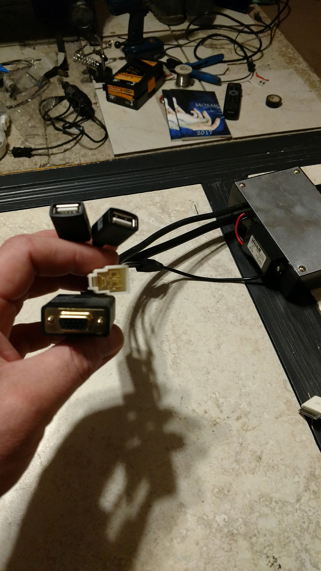
Left side of box, USB charger, VGA to panel switches, Female to connect to vehicle 3 pin connector
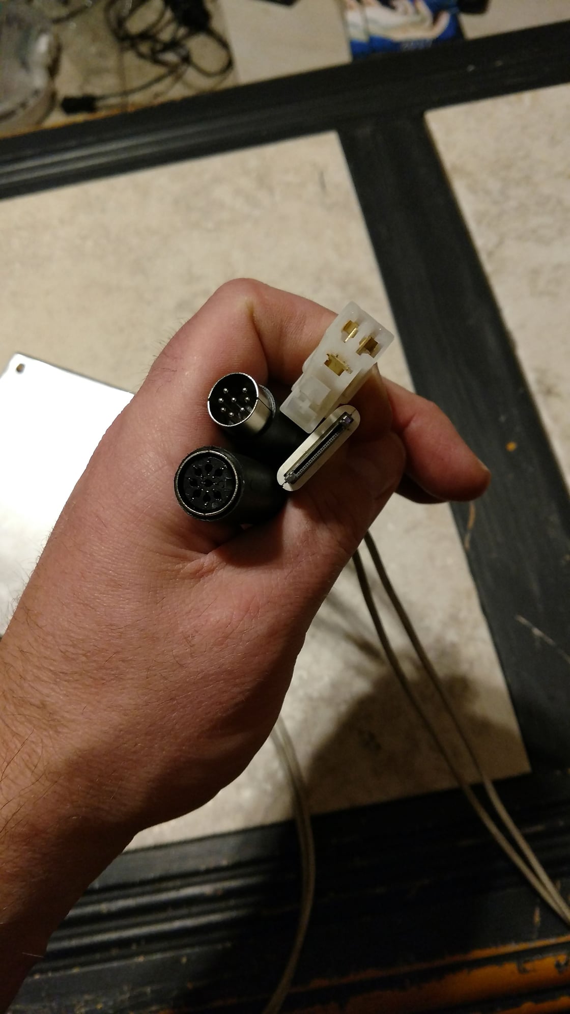
Right side of box, DIN cables from EQ and to tuner, 30 pin ipod cable, male 3 pin connector to tuner
#3
Junior Member
Thread Starter
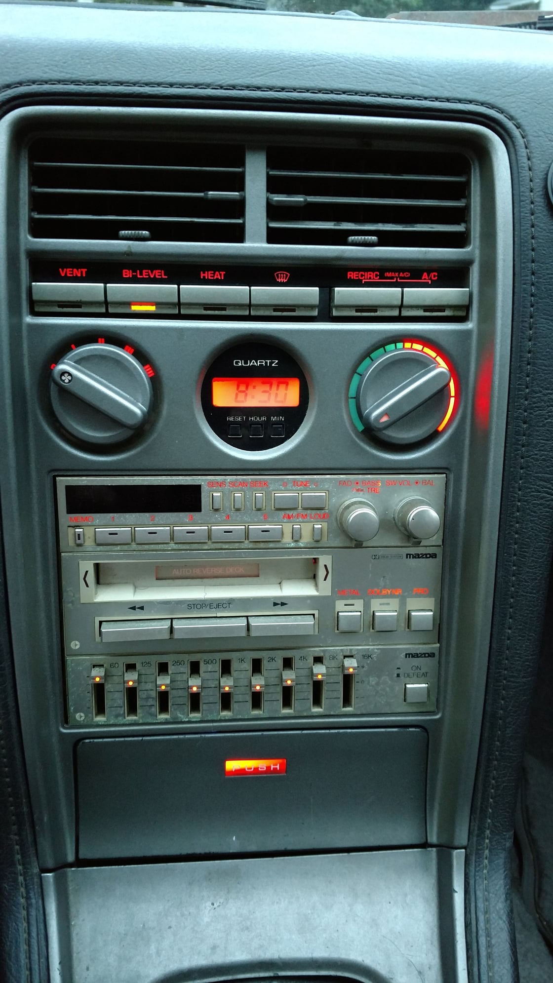
All installed, looks normal
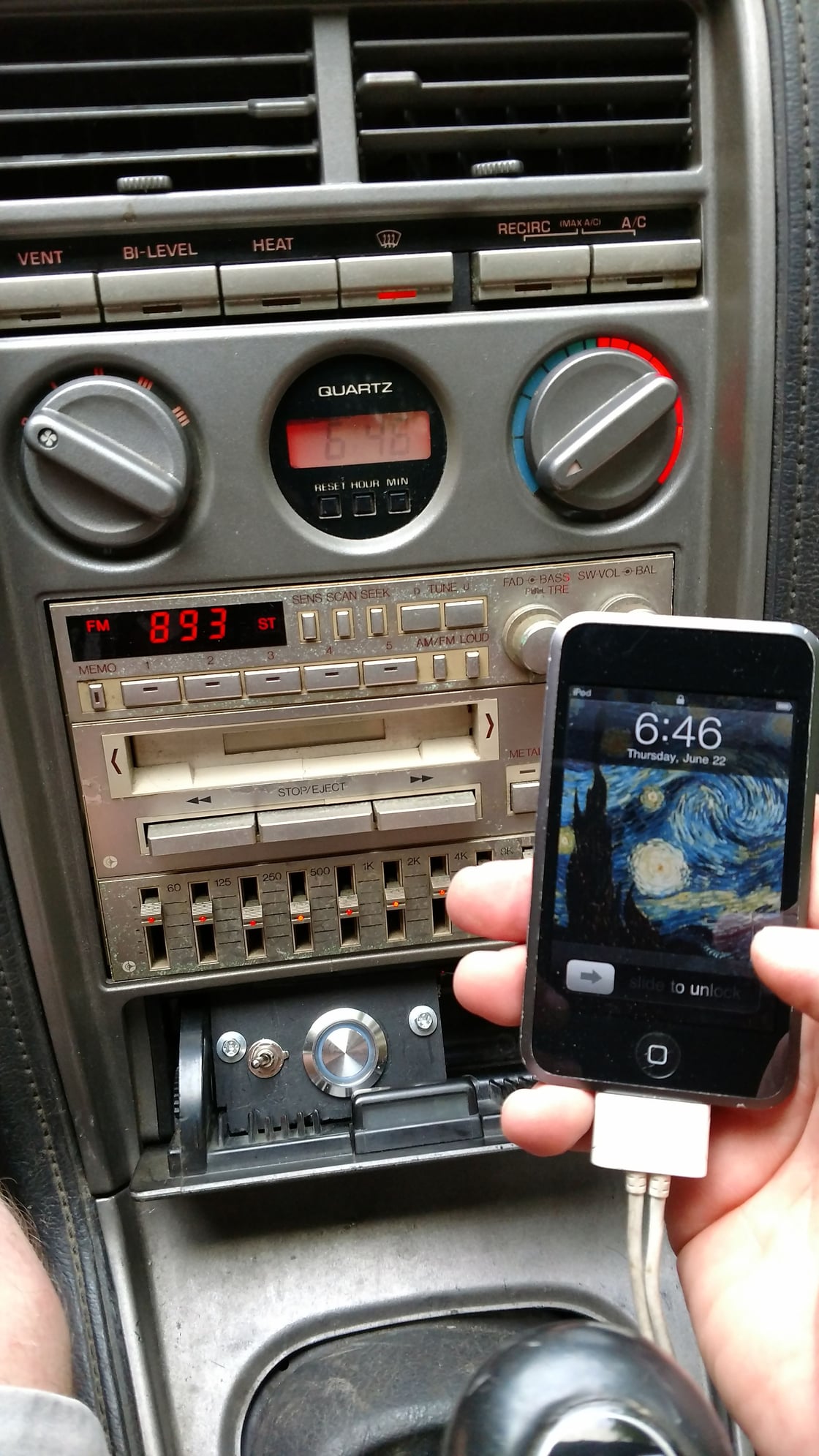
Open ash tray to reveal control switches, left toggle is for bluetooth or ipod audio selection. silver button energizes the relay, swapping the voltage from the tuner to the ipod and bluetooth controller.
The following users liked this post:
shetlen (06-18-22)

