Extending LCA/ballpoint arm thread
 05-07-12, 11:47 PM
#26
The part I'm looking to make also increases the caster. And IDK about you but I've only seen people get 2.4-2.8 degrees of Negative camber, max, with just camber plates.
Making the lower balljoint adjustable lets go far beyond that. So would extending it but it's not adjustable.
Making the lower balljoint adjustable lets go far beyond that. So would extending it but it's not adjustable.
 05-07-12, 11:58 PM
#27

spinning your 'top hats' 45* increases camber with caster and its a lot more feasable than welding plate onto tie rods. also how much more than 2.4-2.8* do you want? my car with just typical coilover camber adjustment is easily over 3.5* proven on a rack.
05-08-12, 12:18 AM
#28
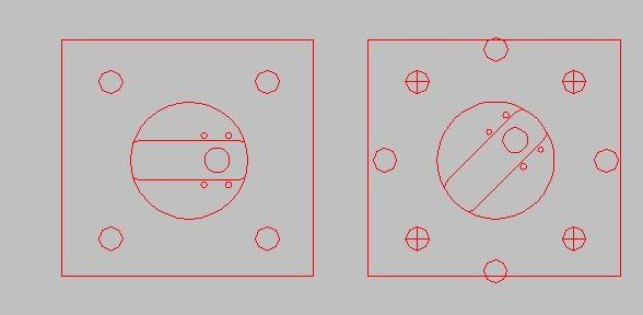
I don't think you're getting how my little diagram works but it still needs tweaks.
But I have thought about increasing caster that way but what about rollcenter.
And also, I just looked at my aligment specs. I got ~2.2* neg camber and well that's nowhere near enough I think.
Sucks that this chassis hasn't been super competitive lately and I think it's cuz those who have wanted to go full on Pro in the sport, end up leaving the chassis behind. I think even the great "Drift Samurai" went to a 2013 Mustang this year.
05-08-12, 04:41 AM
#30
Junior Member
Thread Starter

Join Date: Jan 2012
Location: tasmania, australia
Posts: 25
Likes: 0
Received 0 Likes
on
0 Posts
bum, thats not what i wanted to hear, was banking on it moving the direction of how the wheel travels so it wasn't gunna be a huge issue for my guards! if that makes sense!
05-08-12, 10:16 AM
#31
Dreamin' of Rotary

Join Date: May 2009
Location: Utah
Posts: 145
Likes: 0
Received 0 Likes
on
0 Posts
^^^ Very nice. On a similar subject, has anyone tried moving the ball joint forward to increase caster. If I ever decide to extend the balljoint, I will might as well try moving it forward while I'm at it. Also, I really want to correct the roll center with this little baby.
Problem is tough, how do I make it.

Problem is tough, how do I make it.
They don't even understand why you don't make a REIB design... *sigh*
The radial load rating of the rod end is when it's under TENSION. You put a pure bending load on the rod end and now your highest loaded part is the threaded shank. The threads make perfect stress risers for a crack to start, and the more the rod end is threaded out the higher the loading is. Think of it as a flagpole. It's really really strong pulling it straight out, but you can push the thing over far easier due to the bending moment.
This will probably work for someone that only drifts their car, as it doesn't load up front tires all that much, but I would not want to be braking into a high speed corner with some aero downforce and Hoosiers on those things...
05-08-12, 02:37 PM
#32
The threaded portion of the rod doesn't see that much bending or load. This is a MacPhereson strut design and all the weight goes on the upper mount of the Strut, unless you have a sway bar that is crazy stiff and your springs are relatively soft.
At first I thought you were talking about the bolt itself that goes to the knuckle, seeing as it does see some lateral loads when going through a corner, but if you think about that scenario as well, a good design should have no problem handling the stress seeing as the tie rods are often swapped out for bumpsteer adjustable ones that put a large bending load onto that rod that connects the knuckle to the rod itself.
At first I thought you were talking about the bolt itself that goes to the knuckle, seeing as it does see some lateral loads when going through a corner, but if you think about that scenario as well, a good design should have no problem handling the stress seeing as the tie rods are often swapped out for bumpsteer adjustable ones that put a large bending load onto that rod that connects the knuckle to the rod itself.
05-08-12, 03:19 PM
#33
Dreamin' of Rotary
Join Date: May 2009
Location: Utah
Posts: 145
Likes: 0
Received 0 Likes
on
0 Posts
You're not understanding. Has nothing to do with spring rates.
When you jam the brakes to slow down, the wheel's friction against the ground is what's stopping the car. Somewhere around 80% of braking is done with the front wheels, yeah?
The wheel is connected to the car via the spindle, which is connected to the car via the upper and lower ball joints. Some of the forward load is transfered to the top, but most is still on that lower ball joint, perpendicular to the threads.
I'm sure you've noticed that the control arm mounts to the chassis in two spots.
A heim joint on the end of a tie rod is NOT a rod end in bending, since it is pushing straight outward and pulling straight inward and don't handle any BENDING force.
Last edited by mikerbike; 05-08-12 at 03:22 PM.
05-08-12, 04:15 PM
#34
Dreamin' of Rotary
Join Date: May 2009
Location: Utah
Posts: 145
Likes: 0
Received 0 Likes
on
0 Posts
05-08-12, 06:05 PM
#35

besides the REIB, that picture wont work unless you have a very high misalignment rodend.
with a standard 3/4" bearing/rodend, you get 13* misalignment, which is questionably enough through the suspensions range of motion (will work with stiff springs ~ small travel). on top of that, the stock ball joint is at a 14* angle from the control arm. based on my measurements (with my car/tire height, and ~2" of correction), that 14* angle is ideal to get the most range out of a bearing.
and no, i dont have a complete roll center kit- its halfway done. i'm using a spherical bearing in a cup, and a 3/4"x6" bolt turned down to fit into the spindle. just gotta design the arm part, get it cut+bent, and weld to the bearing cups. been slacking tho
05-08-12, 08:12 PM
#36
You're not understanding. Has nothing to do with spring rates.
When you jam the brakes to slow down, the wheel's friction against the ground is what's stopping the car. Somewhere around 80% of braking is done with the front wheels, yeah?
The wheel is connected to the car via the spindle, which is connected to the car via the upper and lower ball joints. Some of the forward load is transfered to the top, but most is still on that lower ball joint, perpendicular to the threads.
I'm sure you've noticed that the control arm mounts to the chassis in two spots.
A heim joint on the end of a tie rod is NOT a rod end in bending, since it is pushing straight outward and pulling straight inward and don't handle any BENDING force.
When you jam the brakes to slow down, the wheel's friction against the ground is what's stopping the car. Somewhere around 80% of braking is done with the front wheels, yeah?
The wheel is connected to the car via the spindle, which is connected to the car via the upper and lower ball joints. Some of the forward load is transfered to the top, but most is still on that lower ball joint, perpendicular to the threads.
I'm sure you've noticed that the control arm mounts to the chassis in two spots.
A heim joint on the end of a tie rod is NOT a rod end in bending, since it is pushing straight outward and pulling straight inward and don't handle any BENDING force.

I completely over looked that. Thanks for clarifying that. Now that I look back at these products, I can see why they used a sperical plain bearing like this.
http://www.midwestcontrol.com/series.php?id=114
PBM: http://www.gtfactory.jp/cms/page.php?14
Megan Uses standard ball joints:
http://www.meganracing.com/product_d...d=807&catid=26
05-09-12, 02:54 PM
#37
I found them!!! Kinda pricier than other options but the convenience of having all the components necessary is great. Just need to design the arm/plate
http://www.racereadyproducts.com/fk-...-uniball-kits/
http://www.racereadyproducts.com/fk-...-uniball-kits/
05-21-12, 07:37 PM
#38
Full Member
iTrader: (2)
Join Date: May 2010
Location: sacramento
Posts: 184
Likes: 0
Received 0 Likes
on
0 Posts
this thread is great, lotta info in here.
i think i want to make a set in CAD and make them with a heim end, that way i can make it so i have 1-1.5 adjustability and see what i like best and what fits best. once i get around to taking the front of my project car apart and start on the drawing, i will definately post my results in here!
edit:
im also thinkin i will make these little guys as pictured (just the spacers, no ends)so i wont have to modify the stock tie rod and make it a little easier on myself. i plan on running a new OEM rod with a supernow end, as well as a knuckle kit (either PBM or hotline)
Last edited by blindboxx2334; 05-21-12 at 07:42 PM.
05-22-12, 10:40 AM
#39
Dreamin' of Rotary
Join Date: May 2009
Location: Utah
Posts: 145
Likes: 0
Received 0 Likes
on
0 Posts
I don't even own an FC and I'm excited about this!
http://www.gtfactory.jp/cms/e107_plu...topic.php?9099
http://www.gtfactory.jp/cms/e107_plu...topic.php?9099
05-23-12, 11:37 AM
#42
Senior Member
Join Date: Nov 2011
Location: Oklahoma City, OK
Posts: 418
Likes: 0
Received 0 Likes
on
0 Posts
Those look sick as fuuuukkkkk
Might have to break down and buy their set once they're manufacturing them. Nothing wrong with mig welding if it's done by a good welder. Not as pretty as tigging, but structurally it's alright.
I was planning on building my own, but this may be too much for me. Those LCA's look sick.
Might have to break down and buy their set once they're manufacturing them. Nothing wrong with mig welding if it's done by a good welder. Not as pretty as tigging, but structurally it's alright.
I was planning on building my own, but this may be too much for me. Those LCA's look sick.
05-23-12, 07:42 PM
#43
. . .
iTrader: (8)

Join Date: Sep 2008
Location: Quartz Hill
Posts: 241
Likes: 0
Received 0 Likes
on
0 Posts
yeah but those mig welds dont look great. I can mig and I can tig, those mig welds even hid under powder look like ****. Cool product none the less just kinda ugly thats all.
05-24-12, 12:49 AM
#44

Here's my super secret setup. or not.
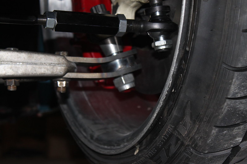
10mm extension, roll center correction, bolts to factory arm. I also have a 30mm wider setup but I really like how this feels right now.
I'm getting 68� of angle and I'm rubbing the LCA. New mods to the LCA should put me at 70�+ of angle. Notched frame rails help prevent **** from hitting.
I also have custom machined upper camber/caster plate.
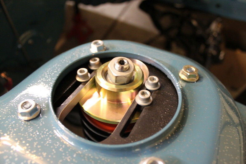
I can change caster now. I don't really change the camber much through the plate because it affects a lot of other stuff. I mostly use to to tune the KPA and scrub on the car at this point.
10mm extension, roll center correction, bolts to factory arm. I also have a 30mm wider setup but I really like how this feels right now.
I'm getting 68� of angle and I'm rubbing the LCA. New mods to the LCA should put me at 70�+ of angle. Notched frame rails help prevent **** from hitting.
I also have custom machined upper camber/caster plate.
I can change caster now. I don't really change the camber much through the plate because it affects a lot of other stuff. I mostly use to to tune the KPA and scrub on the car at this point.
05-24-12, 02:04 AM
#45
Hey George, for that spherical bearing that goes on the lower control arm to the knuckle, how is that mounted up, is it just a threaded bolt and you just sandwich it in-between or do you make a notch on it like a factory balljoint and have the knuckle clamp down on it?
05-24-12, 04:27 AM
#46
Junior Member

Join Date: Jul 2010
Location: new zealand
Posts: 31
Likes: 0
Received 0 Likes
on
0 Posts
Those psm pieces look tough. My setup is just a bit of 15mm flat steel sandwiched between ballpoint adapter and lower arm. Still rub on lower arm though, even with 30mm extended
05-24-12, 11:43 AM
#47
it's strong enough to catch the curbing at ATL backwards and not flinch.
 I was thinking of getting some mazdtrix if my Megan racing ones ever break, but SPL is probably the way to go.
05-24-12, 08:29 PM
I was thinking of getting some mazdtrix if my Megan racing ones ever break, but SPL is probably the way to go.
05-24-12, 08:29 PM
#49
Trash Talk

Join Date: May 2011
Location: Phoenix
Posts: 83
Likes: 0
Received 0 Likes
on
0 Posts
