
Updates on Marc-Andre Bergeron's 13B-PP Rx-8 - Come visit in Montreal!

Thread Starter
Joined: Feb 2010
Posts: 1,660
Likes: 2
From: GTA, Ontario
Updates on Marc-Andre Bergeron's 13B-PP Rx-8 - Come visit in Montreal!
Thought I would post some updates and invite anyone going to the F1 weekend in Montreal to come say hello and check out the car.  Who knows, with the new F1 "power units" we may be the loudest thing at the track!
R.P.M. (Joe) and I, along with our team, have been hard at work for the past 5 or 6 months on the development of Marc-Andre's Rx-8 in CTCC. We had our second dyno session with Sasha of OnPoint Dyno on Saturday and are quite pleased that we were able to improve on power before the weekend. There is still SO much work to be done to get this car competitive in Super Class, but since this is basically a weekend and nights-only project at the moment we've been making the best of the little time we have.
We're still not up to where you'd normally expect the power to be from a peripheral port 2-rotor, but we'll be redesigning our exhaust system after this weekend. Time seems to evaporate into thin air when you work on racecars. Nonetheless, I was shocked at the amount of horsepower and torque we gained from our air box design. From my first CAD renderings over 5 months ago to (FINALLY!) a prototype that we could put through the paces on the dyno...


Transient Slow-mo: https://scontent-a-ord.xx.fbcdn.net/...9c&oe=538D5BD7
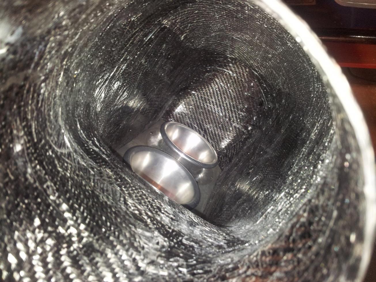
I played around with maybe 10 or 12 different designs for quite a while doing static and transient flow simulations. You can see some things in this particular design (an early one - I didn't take many screenshots), for example the air flow to the first trumpet is choked by the short and abrupt change in direction, so we made the entrance to the carbon fiber air box longer with a more gradual taper. Since I discovered it's extremely difficult to model resonances, air's natural spring qualities, and intake-exhaust overlap pressure equations in the NX Flow software I use at school, I aimed for the best possible airflow path and I guess we'll leave it up to trial and error to get the optimal volume. Honestly I'm not sure how much better we can do than this one, since we ended up with what I would consider huge gains from JUST an airbox.
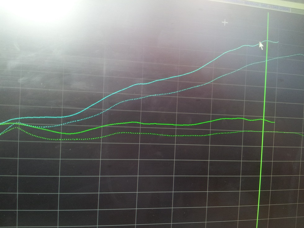
We saw an average of 15-20 whp gain across the entire rpm range, and roughly 10-15 ft-lb of torque. The largest gain was 30whp at ~7000rpm. Fluid dynamics is AMAZING! Again, the airbox is the ONLY difference in these runs compared to our first dyno over a month ago.
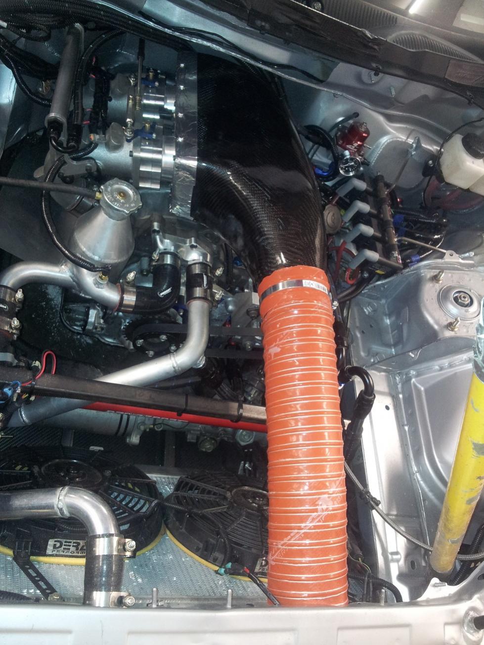
Now that we know this prototype makes jam we'll have to put some time in to smoothing out the rough molding surface from the plastic-wrapped foam that we made the plug out of. Kevin Stittle at C3 (Custom Carbon Composites) is the guy we took the design to to mold, since my original plan of 3D printing a few designs was way over budget... average of $1200 per airbox!
Anyways, you may have noticed the dyno graph stops short of where we were revving to previously. On track at Mosport last month Marc-Andre reported clutch slipping above 9k rpm... We rev to 10k. The AiM data revealed it was almost like a light switch - no slipping anywhere else, but the graph of Engine RPM vs Speed showed a rather sudden increase in rpm as soon as he hit that magic 9k. Same thing was occuring on the dyno so we stopped short at 9,000. We're assuming that the pressure plate in the car was letting go once it revs above that mark, which means we had an awesome excuse to order the 4.5" Quartermaster clutch and flywheel from Mazdatrix. It won't arrive until after Montreal, but Joe and I managed to change the pressure plate out with a custom heavy-duty TII FC one he had at the shop.
Other than that, we're pretty much ready to party this weekend. Here's some pictures from the first event(Not mine!). Luckily Marc-Andre hired a good photographer for the season, since I'm very picky about that, for obvious reasons!
Feel free to follow along on Marc-Andre's page on facebook. We're trying our best to the keep the rotary alive in high-level Canadian Motorsports!
https://www.facebook.com/media/set/?...9966599&type=1


R.P.M. (Joe) and I, along with our team, have been hard at work for the past 5 or 6 months on the development of Marc-Andre's Rx-8 in CTCC. We had our second dyno session with Sasha of OnPoint Dyno on Saturday and are quite pleased that we were able to improve on power before the weekend. There is still SO much work to be done to get this car competitive in Super Class, but since this is basically a weekend and nights-only project at the moment we've been making the best of the little time we have.
We're still not up to where you'd normally expect the power to be from a peripheral port 2-rotor, but we'll be redesigning our exhaust system after this weekend. Time seems to evaporate into thin air when you work on racecars. Nonetheless, I was shocked at the amount of horsepower and torque we gained from our air box design. From my first CAD renderings over 5 months ago to (FINALLY!) a prototype that we could put through the paces on the dyno...
Transient Slow-mo: https://scontent-a-ord.xx.fbcdn.net/...9c&oe=538D5BD7
I played around with maybe 10 or 12 different designs for quite a while doing static and transient flow simulations. You can see some things in this particular design (an early one - I didn't take many screenshots), for example the air flow to the first trumpet is choked by the short and abrupt change in direction, so we made the entrance to the carbon fiber air box longer with a more gradual taper. Since I discovered it's extremely difficult to model resonances, air's natural spring qualities, and intake-exhaust overlap pressure equations in the NX Flow software I use at school, I aimed for the best possible airflow path and I guess we'll leave it up to trial and error to get the optimal volume. Honestly I'm not sure how much better we can do than this one, since we ended up with what I would consider huge gains from JUST an airbox.
We saw an average of 15-20 whp gain across the entire rpm range, and roughly 10-15 ft-lb of torque. The largest gain was 30whp at ~7000rpm. Fluid dynamics is AMAZING! Again, the airbox is the ONLY difference in these runs compared to our first dyno over a month ago.
Now that we know this prototype makes jam we'll have to put some time in to smoothing out the rough molding surface from the plastic-wrapped foam that we made the plug out of. Kevin Stittle at C3 (Custom Carbon Composites) is the guy we took the design to to mold, since my original plan of 3D printing a few designs was way over budget... average of $1200 per airbox!
Anyways, you may have noticed the dyno graph stops short of where we were revving to previously. On track at Mosport last month Marc-Andre reported clutch slipping above 9k rpm... We rev to 10k. The AiM data revealed it was almost like a light switch - no slipping anywhere else, but the graph of Engine RPM vs Speed showed a rather sudden increase in rpm as soon as he hit that magic 9k. Same thing was occuring on the dyno so we stopped short at 9,000. We're assuming that the pressure plate in the car was letting go once it revs above that mark, which means we had an awesome excuse to order the 4.5" Quartermaster clutch and flywheel from Mazdatrix. It won't arrive until after Montreal, but Joe and I managed to change the pressure plate out with a custom heavy-duty TII FC one he had at the shop.
Other than that, we're pretty much ready to party this weekend. Here's some pictures from the first event(Not mine!). Luckily Marc-Andre hired a good photographer for the season, since I'm very picky about that, for obvious reasons!
Feel free to follow along on Marc-Andre's page on facebook. We're trying our best to the keep the rotary alive in high-level Canadian Motorsports!
https://www.facebook.com/media/set/?...9966599&type=1
Nice looking airbox. Fluid dynamics aside, how much of that rwhp do you think is just from colder air? I've seen 30 rwhp gains from just the repositioning of a fan on the dyno on the Mazdee's half-bridge which is why their is 2 air ducts shoving pressurized air from the front air damn right at the ITB's.
thewird
thewird
Rotary Freak
Joined: Jul 2003
Posts: 2,199
Likes: 9
From: Oakville, Ontario
Charles, that airbox is beautiful, sniff sniff. Exactly the type of information that I was looking for. I was looking to build a box for my ITB setup as I felt that it would help and this proves it. I love the flow and the lines. I totally get the issues with making sure you get enough airflow to the front trumpet. This is a concern on mine as well as the strut tower is right in the way. I have done rough calculations on airbox volumes required and they are pretty large and in my case, wont fit into the area available.
I just love the fact that you guys are starting to do some conceptual racecar development. Its an exciting process, especially when you have budget, LOL.
Big thumbs up to Charles and of course Joe.
Eric
I just love the fact that you guys are starting to do some conceptual racecar development. Its an exciting process, especially when you have budget, LOL.
Big thumbs up to Charles and of course Joe.
Eric
Thread Starter
Joined: Feb 2010
Posts: 1,660
Likes: 2
From: GTA, Ontario
Nice looking airbox. Fluid dynamics aside, how much of that rwhp do you think is just from colder air? I've seen 30 rwhp gains from just the repositioning of a fan on the dyno on the Mazdee's half-bridge which is why their is 2 air ducts shoving pressurized air from the front air damn right at the ITB's.
thewird
thewird
Data shows intake temps were about the same for both sessions before and after the airbox is on. Those miata intakes point upward directly above the exhaust, correct? Ours draws air from the other side of the engine without the airbox there. We also have a heat shield over the exhaust.
We repositioned the big fan many times during our first dyno session. If you point the fan AT the intakes, of course you're going to see gains. Is this the same as on-track conditions? No.
Also, why not just make an airbox for those intakes? I realize you'd have to cut the hood but at least then ALL of the air is coming from the rad area.
Thread Starter
Joined: Feb 2010
Posts: 1,660
Likes: 2
From: GTA, Ontario
Charles, that airbox is beautiful, sniff sniff. Exactly the type of information that I was looking for. I was looking to build a box for my ITB setup as I felt that it would help and this proves it. I love the flow and the lines. I totally get the issues with making sure you get enough airflow to the front trumpet. This is a concern on mine as well as the strut tower is right in the way. I have done rough calculations on airbox volumes required and they are pretty large and in my case, wont fit into the area available.
I just love the fact that you guys are starting to do some conceptual racecar development. Its an exciting process, especially when you have budget, LOL.
Big thumbs up to Charles and of course Joe.
Eric
I just love the fact that you guys are starting to do some conceptual racecar development. Its an exciting process, especially when you have budget, LOL.
Big thumbs up to Charles and of course Joe.
Eric

We haven't measured the actual volume of this prototype yet but we'll do that after the weekend is over.
Rotary Freak
Joined: Jul 2003
Posts: 2,199
Likes: 9
From: Oakville, Ontario
Glad to hear this helps in some way, Eric! The average volume I got with the CAD designs within the dimensions that fit in our engine bay is about 8-9L - plenty to account for cyclical intake draw, replenishment, and the pressure reversions back INTO the box. How did you do your calculations for volume? I had difficulty with the calcs because the intake port is never techincally closed at any point, which makes the volume needed for helmholtz equations much more difficult to calculate... I think, anyways.
We haven't measured the actual volume of this prototype yet but we'll do that after the weekend is over.
We haven't measured the actual volume of this prototype yet but we'll do that after the weekend is over.
In the end we wussed out and I built a ton of heat shielding and just stuck filter socks on the trumpets. I still have the paper model of the actual airbox here in my office. It looks like a grossly distorted bread box as it has to fit around the strut tower.
Eric
Data shows intake temps were about the same for both sessions before and after the airbox is on. Those miata intakes point upward directly above the exhaust, correct? Ours draws air from the other side of the engine without the airbox there. We also have a heat shield over the exhaust.
We repositioned the big fan many times during our first dyno session. If you point the fan AT the intakes, of course you're going to see gains. Is this the same as on-track conditions? No.
Also, why not just make an airbox for those intakes? I realize you'd have to cut the hood but at least then ALL of the air is coming from the rad area.
On a side note half-bridge miata makes 232 rwhp on Sasha's dynopac with a capped rev limiter (HP line still pointing up). There is also an exhaust shield, that is like 101 for endurance and heat management.
thewird
Trending Topics
 There's more to an airbox design than fresh colder air... I just said the temperatures were about the same and we made more power by adding a "restriction"
Thread Starter
Joined: Feb 2010
Posts: 1,660
Likes: 2
From: GTA, Ontario
Actually, your post reminded me of a really good quote one my professors got stuck in my head: "An engineers job is to do for 10 cents what any fool can do for 10 dollars."
It's my belief that 'explaining things with numbers' gets you, much more consistantly at least, to an optimal solution when you understand the theory and know the general path you should be on (where to find GOOD information, what applies to this scenario, etc). I'd much rather develop 10 engines to the 290whp mark by following a logical path than get 1 engine to the 310whp mark by blindly exlcaiming "Holy crap, I can't believe that worked!" after spending 10x the money on physical prototypes and dyno testing.
That's just me... but I'm confident eventually through engineering you'd get all 10 engines to the 320whp mark, without spending as much as the guy who built one would have spent doing so. Explaining things with numbers isn't necessarily more complicated... if you understand what the numbers mean lol
Thread Starter
Joined: Feb 2010
Posts: 1,660
Likes: 2
From: GTA, Ontario
I would have to check, but I didn't do the actual calculations, my buddy Dave did and we came out to between 7 and 8 litres in volume. The issue we had was determining where the airbox started, the atmospheric pressures and how much air was required as, exactly as you say, there was always one port open on each rotor. I am using a 4 throat ITB setup and a 1/2 bridge. As well we struggled with the philosophical question, was it just the actual airbox area or how much of the cold air tube should we use, especially if we went with a 4" flexible pipe. So in the end we just did some rough calculations using a 2600 cc piston engine (assumed that 2 rotor chambers were always in action), the rpm we were going to and came up with something like 7.6xxx litres. This we decided would include the actual airbox area plus the cold air tube right up to the filter. The only issue was figureing out how to fit it all in with the available space and attaching it to my throttle bodies.
In the end we wussed out and I built a ton of heat shielding and just stuck filter socks on the trumpets. I still have the paper model of the actual airbox here in my office. It looks like a grossly distorted bread box as it has to fit around the strut tower.
Eric
In the end we wussed out and I built a ton of heat shielding and just stuck filter socks on the trumpets. I still have the paper model of the actual airbox here in my office. It looks like a grossly distorted bread box as it has to fit around the strut tower.
Eric
So you think all that 30 rwhp gain is from the airbox and has nothing to do with the fact that you stopped the hot air that was being sucked from the fans which are blowing directly at it with those Derale fans along with engine heat being radiated directly from below?
But anyway, if its working for yah, keep at it. I tend to look at things with a common sense approach as it saves time getting to results. Looking forward to more updates.
thewird
But anyway, if its working for yah, keep at it. I tend to look at things with a common sense approach as it saves time getting to results. Looking forward to more updates.
thewird
Joined: Dec 2002
Posts: 3,791
Likes: 3
From: Kitchener Ontario Canada
You and your retiree buddy, Dave Dietrich, both scoffed at having rotating assemblies balanced when I built Kens engine. If you had any common sense, you would know that balancing a rotating assembly is the best thing to do for any engine being built. Rotary or Piston.
I have been balancing engines and recommending it to all my customers for years. Probably before you even knew what the inside of a Rotary engine looked like.
Your butchered attempt at a Time attack car is absolutely laughable. Installing tires which stick out the side of the car and rub on the fenders is the ABSOLUTE OPPOSITE of common sense.
Your car would be faster with a 400whp 13B and sort out the suspension and handling characteristic's of the chassis. But instead you build a XXXWHP 20B and immediately think the car will be faster around the track. ----> No common sense detected yet....
You build an ultra low compression engine so you can run high boost on pump gas....WTF?!
That works great for drag cars where off throttle response doesn't matter.
Common sense would point me in the direction of having instant throttle response when you want it for a Time Attack car.
Please before you come on here and arguing with us about common sense. Please reflect on your own.
Firstly, there is no reason to bring up someone who isn't even in this conversation. Anything I say is me and me alone that says it and has that opinion. Dave could care less what is happening in the kid world of time attack. I'm of the opinion balancing an engine with the redline of 8,000 rpm is a waste of money as it serves no purpose. It isn't going to live longer, it isn't going to wear the bearings any less, that is my opinion on the subject. If you want to do it as some sort of precaution, there is really nothing wrong with that and is your prerogative.
As far as the tempurature data, I avoided touching that subject intentionally since I knew it would cause an argument. I'll just say this is one of those cases where a sensor isn't telling you the whole story. And that is all I'm going to say on that subject.
And lastly, if you want to talk about my car you can do that in my build thread as that would be the more logical place to do it instead of here. But in short my car is a street car and was never built to be an ultimate time attack car. Building an all out race car is easy. And response is something I want less of, I don't think you have any idea how snappy the car actually is with all that instant torque, which just breaks the tires loose. The only thing my car needs to be faster is the engine in the right place, a transmission I could depend on, and reliable brakes. Anything else I do to the car in the meantime is experimenting and I've never said its any better then any other setup.
Now having address'd your issues on unrelated topics... My original and only comment is how much of the gains do you think is attributed to the colder forced air coming from the front of the car vs the heat-soaked air at the back of the engine bay or do you believe all the gains are just from the intake box design alone. If you don't know or don't want to talk about it then just say so instead of becoming all defensive. The rotary community is terrible with people attacking each other all the time, its silly.
thewird
Thread Starter
Joined: Feb 2010
Posts: 1,660
Likes: 2
From: GTA, Ontario
Marco, please go play internet rotary god somewhere else... getting real tired of you downplaying everyone else's work in the car community.
Really don't feel like explaining heat transfer properties of turbulent air, ambient conditions from our dyno sessions, and our recorded data to you.
Really don't feel like explaining heat transfer properties of turbulent air, ambient conditions from our dyno sessions, and our recorded data to you.

Rotary Freak
Joined: Jul 2003
Posts: 2,199
Likes: 9
From: Oakville, Ontario
Guys, guys, guys ........ why can't we all get along. I respect Joe and Charles efforts a ton. I have engineered a number of racecars and I know what its like whe you are on the learning curve and developing all kinds of good stuff.
On my RX7 I am still running the stock 4 stud brakes. They do the job of stopping the car. With the right pads and cooling ducts, I never have an issue at Mosport GP track. I have melted the seals out of the front calipers at Shannonville, but then I added better ducts and its fine. The brakes work great and meet my duty cycle, so why change? Of course, I could get some Stoptech tapered 6 piston calipers and 14" floating rotors with biased master cylinders and maybe the car would stop marginally better for longer. That is what is on my Cougar and it does a damn fine job of stopping, but is only a hair better than my RX7's brakes and they take longer to warm up and require constant adjustment as you go through the tank during a race or they lock up.
So why tell this story, in this instance? Because Charles and Joe are working in a different sphere than most of the rest of people modifying RXxxx motors and cars. When you are actually racing versus lapping or Time Attacking, things that look interesting and beneficial need to be tested and validated and in all cases by repeatable benefit versus a clock on every lap. You need to understand what you are doing and why. Does that mean that everything works out, no, but you learn from every theory and if you kept the right records and tracked what was happening it leads you to the best possible solution under the rules. That is the key. Joe and Charles are now operating in races where there are rules, money and very smart men who are doing this for a living and if they don't do as well as possible, other very smart men will come in and take their place.
Marco, is operating in a different area entirely. When you operate without rules, like Sigma and CSCS Time Attack, anything goes and you tend to be more blunt force versus finesse. Marco wants more power, booom, new turbo 3 rotor. More grip, add bigger tires, control stopping better, bang, bigger rotors. It is a lot more of the just get it done and get a result. In fact this is how it is being done at CASC Regional racing right now as well. No rules at all on what you do to a car to make it faster, just safety rules. It is a lot more of run what you brung and the check book wins the day.
Personally, I like the finesse of running within a rule structure so that the engineering is as important as anything, but you have to get to the CTCC or Continental or World Challenge level, before you have rules that control blunt force development. What Marco does is just fine for what he is doing and he is successful at it. What Joe and now Charles are doing is absolutely necessary for the levels they are involved at. Everybody is just fine, now hug and we can move along.
Eric
Marco, please go play internet rotary god somewhere else... getting real tired of you downplaying everyone else's work in the car community.
Really don't feel like explaining heat transfer properties of turbulent air, ambient conditions from our dyno sessions, and our recorded data to you.
Really don't feel like explaining heat transfer properties of turbulent air, ambient conditions from our dyno sessions, and our recorded data to you.
But lol at rotary god comment, nobody knows everything, there is always something to learn. If talking about your intake from a different angle bothers yah that much, I'll leave it alone.
thewird

Thread
Thread Starter
Forum
Replies
Last Post