When you click on links to various merchants on this site and make a purchase, this can result in this site earning a commission. Affiliate programs and affiliations include, but are not limited to, the eBay Partner Network.
Not to much to be done here. !!Non of this has to be done!!
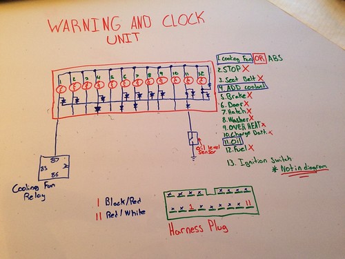
If you want your oil light and cooling fan light to work with your swap, here is what to do! Take the BLACK\RED wire from the harness and splice it into the wire from the 87 pin on the electric fan relay. When the fan is on it will send 12v to the cooling fan light and turn it on. Now connect the RED\WHITE to the oil sensor on the 1j. When the oil level is low it will complete the circuit in the sensor and send 12v to the oil light, turning it on. The "add coolant" light is attached to the potentiometer in the cluster. So nothing has to be modified with that from the warning unit. In this picture you can see a diagram of the harness plug. You can see where the wires should be. These are both "normally open" circuits, so you shouldn't have a problem with different resistance values. In other words, they're either 12v or 0v. Keep in mind that the cooling fan light will slightly raise the amperage on the relay circuit. Make sure you are running a suitable fuse
Here is a port and polish on my 1jz head. This is only 1 of the 5 intake ports. Took me awhile to do one but im very satisfied with the results. Here are the grits i used, if anyone is interested; 100, 320, 400, 600, 1000, 1500, 2000. It takes a lot of time and patience. You have to be very careful around your valve seats. If the metal chuck of your dremel hits, you will most definitely damage it enough for some machine work$$$
This is just a stage 1 port. I removed most of the cast imperfections and made the divider smaller and also added a fine edge on it. I've also done a few other things to the head that i will post when everything is done together. I've gathered some nice toys for the motor . Ive also been working on labling all the sensors on the wire harness. I will have pictures of every single sensor and where it comes from on the ecu.
[IMG]Untitled by mitchell.azevedo, on Flickr[/IMG]
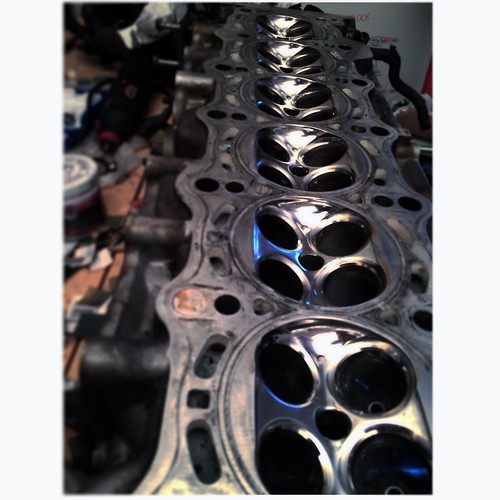
more polishing on the 1j Still need to machine valves, valve seats, port/polish exhaust ports and the get the head cleaned. I got into creating carbon fiber parts. I've made few parts for other cars but not for the rx7 yet. I will be uploading everything i make and they will also be available to buy. stay tuned guys
Cleaned up the head, polished the valve cover and made a carbon spark plug cover. She's looking really pretty now Cant wait for the warm weather to come!
what do you use to polish things like the valve cover i can't quite get my parts to a nice shine. there polished but not shining like id like them to yours looks really good.
I sand all way to 2000g with sand paper. I start wet sanding at about 320g. If its not that shiny but you cant really see any scratches go back to 1500 and then 2000 again. All those small scratches make it haze at the end. Then i use "mag and aluminum polish" haven't tried anything else so i cant compare, but it seems to work well. Polish three times with a wool wheel on a drill and you should have a mirror finish! *Take your time on all the grits*
Been awhile since ive posted. Here is a quick update on the build. Decided to clean the head. After doing some searches i found that Cascade is a good cleaner for aluminum cylinder heads. I filled a large container with warm water, and poured the cascade into the head. Waited for about 20 min, and began to scrub with an old tooth brush. Only took about 5 minutes to get rid of about 80% of the caked on oil. It also got most of the carbon build up in the exhaust ports. This is a great/cheap method and a good parts cleaning solution for aluminum parts. If you really wanted to, you could probably throw a 4 cylinder in the dishwasher and achieve the same result. Theirs still a bit of oil left in the hard to reach places, but every time i drain and refill it seems to slowly break it down. Here are some pics of the process
So ive been hearing a lot of rumors about how the vvti wont fit with most swap kits due to the different mounting points on the passenger side (usdm). But i realized that it actually has the mount points for the NON vvti as well. So i decided to just try it out and if all went bad, i would just fab one up for the left side. I got my mount kit from Xcessive manufacturing. I know of two others who make this swap. Small time guy with a company called futurefab, and the more expensive kit from Tech2Motorsports. I decided to go with xcessive because of the deal i snagged. Otherwise i would have considered Futurefab. Ive got the engine brackets, motor mounts, and frame spacers. Spacers will be needed to space the sub frame, to drop the motor another inch for hood clearance. The mounts are made with 80A bushings and are available in 65A. Heres a look at the kit (All parts will have to be bought separately).
The best way to go at this, is to install the motor mounts first. Then install the motor brackets on the mounts in the engine bay. Don't torque them, leave some play to adjust to the mounting points on the block. Drop the motor in slowly and bolt up one side. Then slowly adjust the height down or up to mount the other side. Its best to do this with a second person, but it is do able by yourself. Its extremely difficult to mount the brackets to the block and drop them on the mounts. That is what i tried to do the first time, and got no where. So ignore that fact that the brackets are on in the picture.
So this is what it looks like bolted in. Theirs lots of room left over in the engine bay for the intake manifold and exhaust manifold. The only thing that im worried about is the upper mount turbo touching the hood. Overall the xcessive kit is awsome and everything went well. Ill post something up for the spacers because theirs some welds you have too cut.
Here is an update on the Xcessive swap kit. So in order to have proper clearance with the hood and the jz, I'm going to have to drop the subframe. Here is a step by step on how to do this (This process is much easier if you remove the front sway bar and the steering rack). Start by removing the nuts on the 4 bolts that attach the frame to the subframe, they are located under the subframe. Keep in mind that these are the only things holding the subframe up , considering you've dropped the power steering... so make sure you have something under the subframe to catch or hold it while you unbolt it. Now cut the tact welds on the 4 bolts (check below for pics). The bolts will have to be banged out, i used a small sludge hammer. Once the bolts are out you will replace them with the ones from the swap kit. You won't be able to use the OEM ones again because they are too short.
Note that there are dowel pins located with the back two subframe bolts. Two of the spacers from the kit have the holes with the seats to properly fit and accommodate with this modification. Take a look at the picture below to see how the spacers are placed. Lightly tap the spacer onto the dowel pin, while ensuring that the hole on the spacer is lined up with the hole on the subframe. Now place the dowel pin from the swap kit, in the top of the spacer. I have not put the subframe back on yet, because I'm currently prepping the bay for primer, but when i do i will post more pictures. If you don't have a jack you'll need a friend to help you out!


 11-11-14, 12:05 AM

 Untitled by mitchell.azevedo, on Flickr[/IMG]
 . Ive also been working on labling all the sensors on the wire harness. I will have pictures of every single sensor and where it comes from on the ecu.
 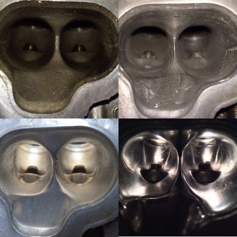 Port by mitchell.azevedo, on Flickr[/IMG]
 Untitled by mitchell.azevedo, on Flickr[/IMG]
 Still need to machine valves, valve seats, port/polish exhaust ports and the get the head cleaned. I got into creating carbon fiber parts. I've made few parts for other cars but not for the rx7 yet. I will be uploading everything i make and they will also be available to buy. stay tuned guys
 Untitled by mitchell.azevedo, on Flickr[/IMG]
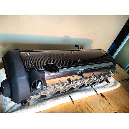 Untitled by mitchell.azevedo, on Flickr[/IMG]