
4-Rotor FC Build

partly why i would like to see how much work it would take to adapt the 2 stock shafts. i'm not sure how PPRE and the other shops manufacture their shafts but you see how easily things can get a little out of control when you want everything perfect.
being a little offcenter is better than milling the lobes down too far as you said. remember that the stroke isn't super important as the apex seals springing will be taking up the slack. normal wear of the housings would actually be similar to what you may be fighting.
if you haven't worked the journals yet i would clamp them down tighter to keep deflection to a minimum, as well as close to the portion your machining as possible, which i'm sure you're already trying to do.
Last edited by RotaryEvolution; Dec 5, 2011 at 05:31 PM.


John, my question earlier on annealing left me baffled, but your clarification later on of thermal stress relief makes sense. That's what I thought you were talking about.
Are you working with the original centers? If so, I think one might want to pursue machining a true diameter some wheres along the straight section, near the middle that doesn't affect function, for a steady rest. Grinding, or some sort of hand truing with an indicator, might be necessary. Then move on to true the journals and then the offsets. If the steady rest relief is cut in a non-functional area and has plenty of adjacent functional area, you should be OK.
Are you working with the original centers? If so, I think one might want to pursue machining a true diameter some wheres along the straight section, near the middle that doesn't affect function, for a steady rest. Grinding, or some sort of hand truing with an indicator, might be necessary. Then move on to true the journals and then the offsets. If the steady rest relief is cut in a non-functional area and has plenty of adjacent functional area, you should be OK.

there's already companies that sell 4 rotors, and in your local country much closer. would be nice if they were affordable for most people but i doubt that's going to happen. you can probably get one setup and running for about a minimum of $25k while doing a lot of the work yourself. IIRC PPRE sells the kit for $13000.
http://www.pulseperformance.co.nz/in...p?page=product
http://www.pulseperformance.co.nz/in...p?page=product
For $70000 I could probably gold plate my car and still have change lol.
the steep prices are for complete running engines, tuned, with engine management systems, wiring, injectors, custom ITBs, manifold, etc.
considering this is a deflection effect i figure we are talking thousandths, there's a bit of room to work with in that respect.
Thread Starter
Joined: Oct 2010
Posts: 605
Likes: 13
From: The Netherlands
John, my question earlier on annealing left me baffled, but your clarification later on of thermal stress relief makes sense. That's what I thought you were talking about.
Are you working with the original centers? If so, I think one might want to pursue machining a true diameter some wheres along the straight section, near the middle that doesn't affect function, for a steady rest. Grinding, or some sort of hand truing with an indicator, might be necessary. Then move on to true the journals and then the offsets. If the steady rest relief is cut in a non-functional area and has plenty of adjacent functional area, you should be OK.
Are you working with the original centers? If so, I think one might want to pursue machining a true diameter some wheres along the straight section, near the middle that doesn't affect function, for a steady rest. Grinding, or some sort of hand truing with an indicator, might be necessary. Then move on to true the journals and then the offsets. If the steady rest relief is cut in a non-functional area and has plenty of adjacent functional area, you should be OK.
This is basically what's happening at the moment, but I'll fix it.

Well there isn't a lot of room really, a untrue stroke would also affect the rotor gear backlash which does all sorts of bad things. After carefull machining doing everything I could to prevent deflection the stroke still ended up being 0,14mm's off, that's 5,5 thousandths. That's way too much. There is a lot on the line here, a failing engine gets expensive fast with a 4-rotor so I'm not taking chances by taking the easy route fabricating the shaft.
Last edited by John Huijben; Dec 6, 2011 at 11:30 AM.
try assembling the front lobes and use that as a center support and use a lower cut speed.(oops, forgot you are running a 90* offset so that won't work)
worst case you may have to manufacture some weights for the bearing lobes to balance the assembly during machining. another crappy thing i wouldn't have thought would be necessary and why i suppose the shafts really are that expensive to produce in low quantities. it's good that you have foresight and didn't ruin the shaft.
could try assembling the front half and check, it may give the shaft enough structural rigidity. or make a jig to reinforce the shaft towards the front.
this is where a 180* 2 sided front lobe would come in handy for a center support. wouldn't help for the front rotor bearing surface however, that is going to be a complex one without the assembly balanced, or machined off the shaft seperately.
a few extra ideas anyways.
Last edited by RotaryEvolution; Dec 6, 2011 at 11:45 AM.

Joined: Mar 2001
Posts: 31,835
Likes: 3,233
From: https://www2.mazda.com/en/100th/
Thread Starter
Joined: Oct 2010
Posts: 605
Likes: 13
From: The Netherlands
Fixed it 
Made a piece with an eccentric hole in it that fitted over a main bearing surface with some set screws. Then testmachined the eccentric surfaces, measured it, noted the dimension, adjusted the alignment by tightening the set screws and locating the insert, re-machined it and done, bang-on within 0,01mm's accurate
Machining time was about 10 minutes. Making sure everything was properly aligned and machined properly took me a few evenings.
http://www.youtube.com/watch?v=X1nr3...el_video_title
Fixed it
Made a piece with an eccentric hole in it that fitted over a main bearing surface with some set screws. Then testmachined the eccentric surfaces, measured it, noted the dimension, adjusted the alignment by tightening the set screws and locating the insert, re-machined it and done, bang-on within 0,01mm's accurate
Machining time was about 10 minutes. Making sure everything was properly aligned and machined properly took me a few evenings.
I was thinking more about your issue and had thought of proposing the same solution and using the steady rest.
I guess us mechanics think alike. I figured you would find a solution.
Last edited by user 893453465346; Dec 10, 2011 at 04:20 PM.


Thread Starter
Joined: Oct 2010
Posts: 605
Likes: 13
From: The Netherlands
It has the same firing order as the 787B, so a 1-3-2-4 firing order with even 90� intervals. The construction of the e-shaft is different than other e-shafts, this design has some benefits and drawbacks. basically it should be stronger but assembling the engine is a bit tricky.
Excellent build! I was astonished at all this awesome work using just manual machines. Keep up the great work! 
Not stirring up the dust, but a turbulent port with a baffle inside is going to flow worse than a straight open turbulent port. This does not indicate a bigger outlet is better vs. a more linear port exit like this setup is using. While my design is a bit different, it is similar in many ways. I've gained torque production vs. a standard turbo sleeve, and its still flowing good enough to make 475rwhp on my 20b. This should be enough to prove it works excellent.
good way of making me a believer. as i said above i did see the differences from the port sleeves in place and swapped with turbo port sleeves. i'm not sure what design you used, whether you did modifications at the same time, rebuilt the engine and then dynoed it immediately, or whatever.
i'm just curious how you went about getting accurate results, it's obvious you don't want to discuss that though for some reason, which is probably variables.
i'm just curious how you went about getting accurate results, it's obvious you don't want to discuss that though for some reason, which is probably variables.
Senior Member
Joined: Nov 2008
Posts: 357
Likes: 0
From: Czech republic


Thread Starter
Joined: Oct 2010
Posts: 605
Likes: 13
From: The Netherlands
Yeah, me too.
Progress is coming along slowly because all the machining on the e-shaft takes ages because of the needed accuracy and the older manual machines I'm using. I've also been working on my chassis dyno, I'm retrofitting a very old chassis dyno from the 50's with some friends, which also takes up a lot of time.
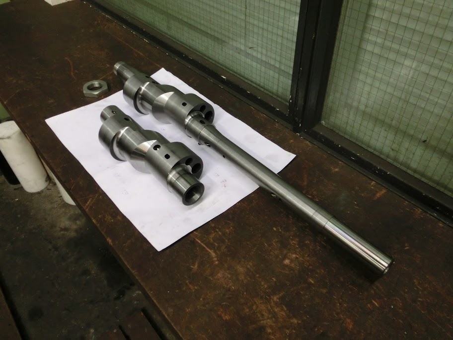
Anyway, the e-shaft is now pretty much done, all is left is nitrating and grinding, which I can't do myself so it's out of my hands now. I sure hope it's going to be ok.
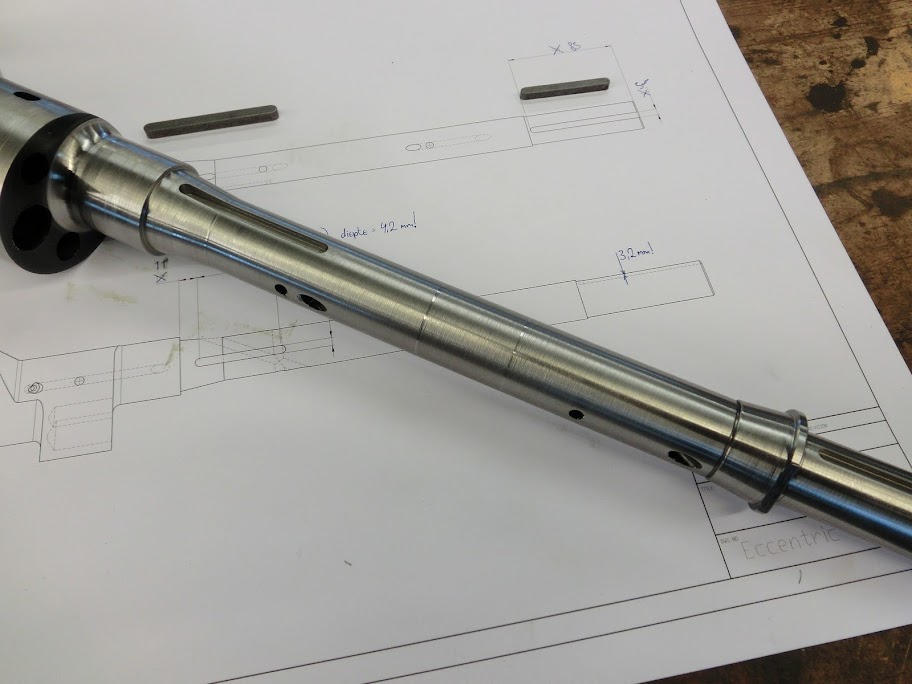
The last machining step, milling the keyway for the front counterweight and such

Checking to see if I didn't screw it up, always very exiting
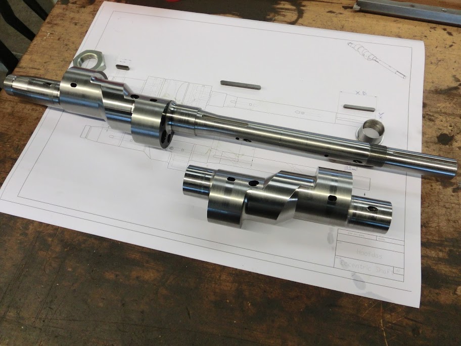


The conical piece on the right is screwed onto the shaft. This locks the slip-on piece together with the e-shaft. So the slip-on piece is positioned using the key that's in the e-shaft, and it's then locked in position using the locking piece. This makes sure it can't slide off or move around when the engine is running.
Progress is coming along slowly because all the machining on the e-shaft takes ages because of the needed accuracy and the older manual machines I'm using. I've also been working on my chassis dyno, I'm retrofitting a very old chassis dyno from the 50's with some friends, which also takes up a lot of time.
Anyway, the e-shaft is now pretty much done, all is left is nitrating and grinding, which I can't do myself so it's out of my hands now. I sure hope it's going to be ok.
The last machining step, milling the keyway for the front counterweight and such
Checking to see if I didn't screw it up, always very exiting
The conical piece on the right is screwed onto the shaft. This locks the slip-on piece together with the e-shaft. So the slip-on piece is positioned using the key that's in the e-shaft, and it's then locked in position using the locking piece. This makes sure it can't slide off or move around when the engine is running.
