When you click on links to various merchants on this site and make a purchase, this can result in this site earning a commission. Affiliate programs and affiliations include, but are not limited to, the eBay Partner Network.
What material are you using 6061 or 7075? A billet that size can be pretty steep depending on specs. At least you got some use out of the messed up one.
I haven't seen that type of chuck before, is that a jobber drill in a chuck, end mill in a collet or something else? Looks like a drill bit in a collet, which is interesting.
Also, back to that exhaust, what engine was it for? Congrats on getting the house buttoned up!
Im actually not sure what alloy it is. I actually have a few of these large 600x400x100 blocks that I once saved from the scrap container, so these were pretty much free, but I don't know the alloy. It's difficult to machine because it's very gummy, it really likes to stick to the endmill.
It's just a normal HSS Drill in a collet by the way. We only have one ISO 40 drill chuck, so I used that for the centerdrill and used collets for the drills. That way I can measure and set all the tool lengths before I load the material and start the program.
That exhaust was for a toyota 2GR-FE, it's a V6, 3.5L quad vvti.
Right, so I started on attempt 2
I changed some things in the cad model, and tried a differend endmill (Used coated carbide before, which gummed up a lot, using uncoated HSS now). and different toolpaths, more rpm's, and deeper but shallower cuts. Went really well, cutting time was about half of last time, and it looks so much better.
And it fits perfecty aswell, all bolt holes line up nicely, and it fits snugly over the dowels.
So that's good. Hopefully I can find some time next week to flip it and do the front side, it's going to be awesome!
Finished the rear side today, starts to at least look expensive.
So I mounted a front iron on the mill, aligned and zero-ed it, put the cover on there and started roughing in the front side. Lot's of material to remove. Hopefully I can finish the front side tomorrow
Yeah it's an oldie, early 90's, 432 control. It does still cut round holes within 0.01mm though, it's just so slow. I'm not complaining though, up untill a few months ago we only had a chinese manual mill, so this is heaps and heaps better. The chinese one gave up and broke down, so my boss let me look for another mill, and I really wanted a CNC, but a fully enclosed VMC is inconvenient for us because we do a lot of longer shafts and weldments and stuff, and with this we can have stuff sticking out with the enclousure doors open, and swivel the head, or use the horizontal spindle. Pretty versatile machine, really happy with it.
Finished the front cover, went from 10 to 1.2kg's:
Fit's perfect :-) Now I can start on the piece that bolt's on that holds the oil pump and alternator.
Yeah it's an oldie, early 90's, 432 control. It does still cut round holes within 0.01mm though, it's just so slow. I'm not complaining though, up untill a few months ago we only had a chinese manual mill, so this is heaps and heaps better. The chinese one gave up and broke down, so my boss let me look for another mill, and I really wanted a CNC, but a fully enclosed VMC is inconvenient for us because we do a lot of longer shafts and weldments and stuff, and with this we can have stuff sticking out with the enclousure doors open, and swivel the head, or use the horizontal spindle. Pretty versatile machine, really happy with it.
It'll last forever with little to no special attention. In the several years I worked with a Maho I had 1 failure with a plastic gear in the spindle transmission. Made a new one and off we went.
Very nice! Is that Maho a full on CNC or conversational? I have quite a lot of experience with Hurco conversational CNC machines and that part is doable in that mode (they can also be run in NC mode just lake any other CNC machine). Whichever, very nice machine work.
It's a full cnc, doesn't do conversational. There are a few canned cycles for some simple stuff though, but you're stuck with G-code. The machine does have handwheels (Not mechanically linked to the ballscrews, but with sensors in them) that will let yo do manual machining. For anything that isnt super simple I usually bring out the cam. The mill is wired to the network, so whenever my laptop is connected to wifi I can either send programs over, or run the machine in drip feed mode.
I'll try to start on this next weekend:
Takes a pretty big billet if I want to machine it from one piece, so I might machine the bottom plate and the brackets seperatly, and then weld it, and machine the important mounting faces flat to size, but we'll see.
Also slowly working / thinking on some other stuff. Most people will call me crazy, but I'm debating to convert the engine to side port. Not entirely sure though, but it makes a lot of things much easier. Legaly registering and driving the car around is one, and track days aswell. The brapping and fuel consumption is not the big issue, noise is. And It would be fun to mess with a turbo again, which I know, can be done on a PP, but much easier on side ports.
But that causes a problem, the front and rear rotor would have 2 small primairy's and 2 large secondaries, like usual, and the middle 2 rotors would have 4 primaires. I think the few people who run a side port 4rotor just have it like this, and therefore tune the middle 2 rotors different from the front and rear one. Could work, but not the best solution. Maybe, since I can do some machining now, that I can come up with something better
Not sure yet how though. I have seen some drawings of side housings, machined from billet, that have a removable wear-sleeve. This allows the machining of the coolant grooves. Also aluminium can be used for the mayority, and nitrated cast iron for the wear plates. Could work, but not sure if the wear plates only being held on the outside perimeter will cause problems. And it's not that cheap. The aluminium billet material for 5 side housings will cost around 700 euros, and then I will need cast iron aswell. But only doing the middle one and leaving the rest stock is also an option.
Maybe machining the cast iron wear plates first, and then casting aluminium around it is also possible. The cast iron part could have dovetails machined on them so the aluminium will lock it in place. It wouldn't be removable anymore though, so the heat treat would have to happen before casting, so a normal nitrating won't work, with casting you need to leave a lot of material for finishing, and nitrating is very shallow. Maybe carbo-nitrating.
Would look something like this:
Anyway, Im rambling. Maybe it stays PP, it does win at making awesome youtube video's and drawing attention.
From what I have seen, most side ports use 12A primary housings with the tall ports, or some make the runners for the intake all the same size and fill the secondary ports with a little epoxy to shrink them down. I believe they also try and port the primary plates to have the same timing as the secondary plates.
You may want to give PPRE a call because Mad Mike's MX5 runs side ports, so they may have an easy answer.
There's no way that dove tail joint is going to be assembled in the contour you have shown. I've thought down this rabbit hole and have my own ideas. Think about it more John, it's staring you in the face. I don't have the wherewithal but the solution is there, and you are on the right track.
From what I have seen, most side ports use 12A primary housings with the tall ports, or some make the runners for the intake all the same size and fill the secondary ports with a little epoxy to shrink them down. I believe they also try and port the primary plates to have the same timing as the secondary plates.
You may want to give PPRE a call because Mad Mike's MX5 runs side ports, so they may have an easy answer.
Well, those are 2 options yes. I think using 6-port iron's and blocking off the aux ports is easier though. But that's plan B for now.
Originally Posted by TonyD89
There's no way that dove tail joint is going to be assembled in the contour you have shown. I've thought down this rabbit hole and have my own ideas. Think about it more John, it's staring you in the face. I don't have the wherewithal but the solution is there, and you are on the right track.
I wonder what you mean and what your solution is. I was thinking about not assembling it, but cnc machining the cast iron wear plates and then casting aluminium around it. I did a little more fiddling, modified the design and designed the casting patterns. I have no idea if it will actually work, but to test it wouldn't cost a whole lot except time, so maybe I'll have a go at it. If anything I'll get an interesting weekend out of it.
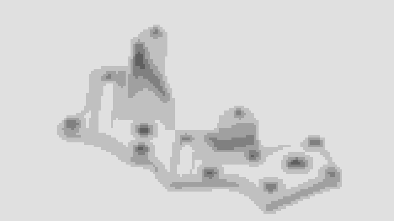
I did start on the dry sump pump mounting plate. Had some other stuff aswell so didn't finish it. Still need to weld and machine the mounting locations.
What are the issues running a full faced iron side housing face so the usual dowels hold the face in place and you just need to o-ring seal the intake port and the inner & outer periphery?
You could even machine the faces from Mazda side housings so you get the zoned differential nitriding.
[QUOTE=John Huijben]I wonder what you mean and what your solution is. I was thinking about not assembling it, but cnc machining the cast iron wear plates and then casting aluminium around it. I did a little more fiddling, modified the design and designed the casting patterns. I have no idea if it will actually work, but to test it wouldn't cost a whole lot except time, so maybe I'll have a go at it. If anything I'll get an interesting weekend out of it.[QUOTE]
I misunderstood. I thought you were first resurfacing irons. I have thought for a long time about making the iron as you have drawn and adding the sides after the fact. I was thinking of holding it in place with a shrink fit. Leave the dovetails but only have taper on the outside, clear the inside edge so it will work when shrunk
Use two or more tapered "tracks". It will work even going through the water jacket ribs or just one inside and outside.
Figure out the expansion difference for saaaay... aluminum side housing at 400 degrees and the cast iron plate frozen with dry ice at the minimum distance across the waist of the figure eight. Make tapers accordingly and for the clearance you gain at that dimension (plus a little room for assembly. Taper will be slighter on the inside angle than on the outer. Or, reverse the side the angle is on and the process if you think it will be more desirable.
I bet some high quality aircraft sealant and assembly in an arbor press would yield excellent results.
WOW! I've been on here 2 years now and just found this!? You sir are very talented. Makes me feel almost incompetent haha. I can't wait to see more updates. Once its done you should get a spotlight in every car magazine around the world!!!
What are the issues running a full faced iron side housing face so the usual dowels hold the face in place and you just need to o-ring seal the intake port and the inner & outer periphery?
You could even machine the faces from Mazda side housings so you get the zoned differential nitriding.
Well it could work. But I think that, by the time the stock piece has been cut and machined flat, that the wear face probably isn't perfectly straight anymore, so it would need flattening and nitrating anyway. So maybe easier to start from a new piece of material. And finding good end housings is getting harder around here.
Originally Posted by TonyD89
I misunderstood. I thought you were first resurfacing irons. I have thought for a long time about making the iron as you have drawn and adding the sides after the fact. I was thinking of holding it in place with a shrink fit. Leave the dovetails but only have taper on the outside, clear the inside edge so it will work when shrunk
Use two or more tapered "tracks". It will work even going through the water jacket ribs or just one inside and outside.
Figure out the expansion difference for saaaay... aluminum side housing at 400 degrees and the cast iron plate frozen with dry ice at the minimum distance across the waist of the figure eight. Make tapers accordingly and for the clearance you gain at that dimension (plus a little room for assembly. Taper will be slighter on the inside angle than on the outer. Or, reverse the side the angle is on and the process if you think it will be more desirable.
I bet some high quality aircraft sealant and assembly in an arbor press would yield excellent results.
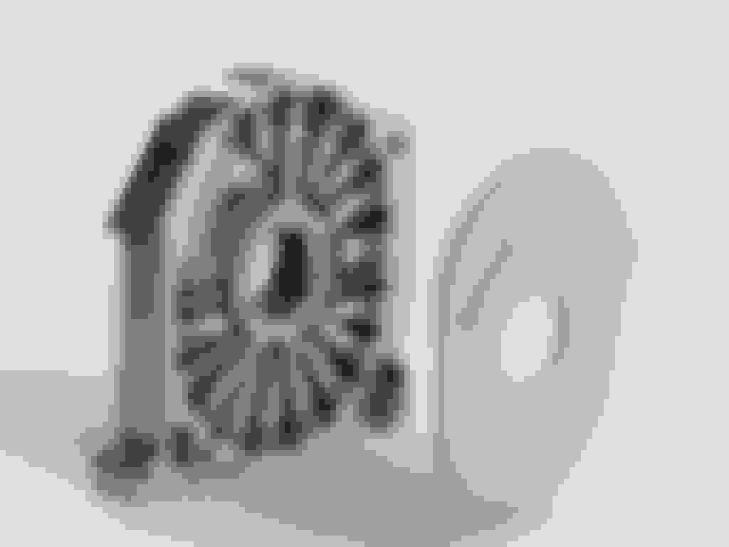
Could actually work. Heating a rotor housing to about 300 deg C will cause it to expand about 0.8mm so it can be expanded to fit over a small dovetail. The outside perimeter isn't the problem though, because if the wear plate is a little bit thicker than the pocket in the machined piece, than the rotor housings will clamp it in place. I was wondering about how to fix it in place a the inside bore, This seems like a simple solution:
So, after looking into casting some more, I figured that maybe it's better to spend some more on billet material and just machine it. I think the chances of succeeding are better and it's probably takes less time. It's a pretty complex looking piece, but most of the machining operations are not that difficult, lot's of 2D contours and some boring. I drew up this for now:
I think I will try and do the 2 intermediate housings and the center housing first. They are pretty much the same, the center one just has the mounting for the stationairy gears and an added oiling hole. I designed it so modified stock rear stationairy gears can be used. This will be more rigid and better than the usual solution which uses a key and a circlip to keep the stationairy gear in place. The housing itself will be a simple 6082-T6, and cast iron for the wear plate. The stock wear surface is a simple cast iron, which is about 400HV after nitrating. I think it's GG25 or similar. I think I will try and use GGG60, a ductile iron with a higher tensile strength. It's about 600-650HV after nitrating.
The front cover is starting to shape up aswell. Need to machine the front face and the mounting points, and then machine the tensioners. Almost done
I noticed in your CAD drawing that the intake ports are at a 45 degree to the bottom instead of the usual straight up and down. Is that for better airflow and tumble into the ports?


 12-30-16, 11:58 AM