I'm back in the 1st gen game... My new 1980
 02-10-15, 10:53 AM
#101
It's WAY different.
First of all, the pulley and hub are a factory matched set. When you swap a different pulley on there, it could be as much as 7 degrees off. Karack mentioned this on the forum first to alert everybody who may have swapped a pulley or was thinking about it. I've seen this myself.
Second, the GSL-SE had a Leading timing mark at -5 degrees, not 0TDC like a 12A. A stock GSL-SE distributor advances a little further than a 12A dizzy for this reason, to make up for this, so they both arrive at about the same total mechanical advance of around 20 degrees at 4k RPM and up. Notice I didn't mention vacuum advance. Important to keep these different systems separate while you're checking total mech advance.
You need a factory matched pulley and hub set. One from a 12A can work but then you need to mark it for -5 degrees and also change the factory Trailing mark to whatever split the GSL-SE had (I think 15 degrees). Then line up and stab a stock GSL-SE dizzy and check it with a timing light once you get it running and warmed up.
Another pulley+hub option would be from an S5 NA. One of their bolts is offset 5mm to make it idiot proof so it only goes on one way. These are plentiful and will work correctly for you (as long as they are 100% factory matched).
Sound like a lot of steps? See that's why I wouldn't bother with an EFI swap into... Oh wait I'm doing it again. Ok, good luck! You'll get it figured out.
 02-10-15, 02:13 PM
#102
Moderator
iTrader: (3)
Join Date: Mar 2001
Location: https://www2.mazda.com/en/100th/
Posts: 30,829
Received 2,597 Likes
on
1,845 Posts
Ive had five FCs and the RX8 so I guess its what im used to. i Iike the sudden power burst feeling a carb gives you when you stomp the gas, but EFI reliability and consitancy over rules that for me. If i ever have a track only car or a stripped weekend beater it will be ported with a 51 IDA.


 02-21-15, 09:54 PM
#107
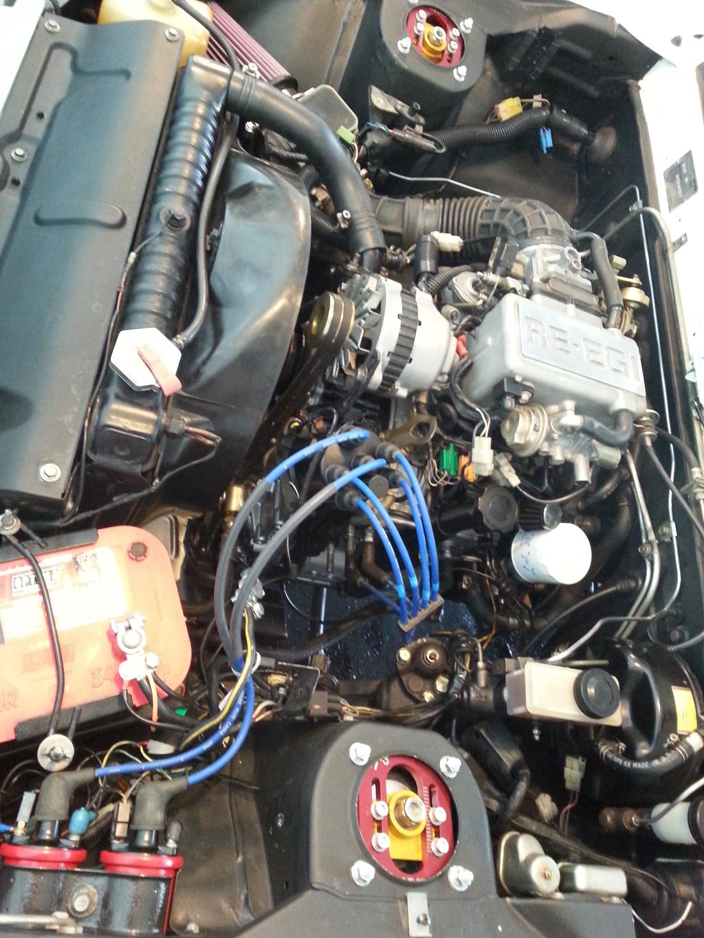
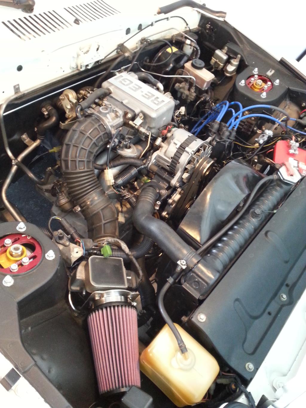
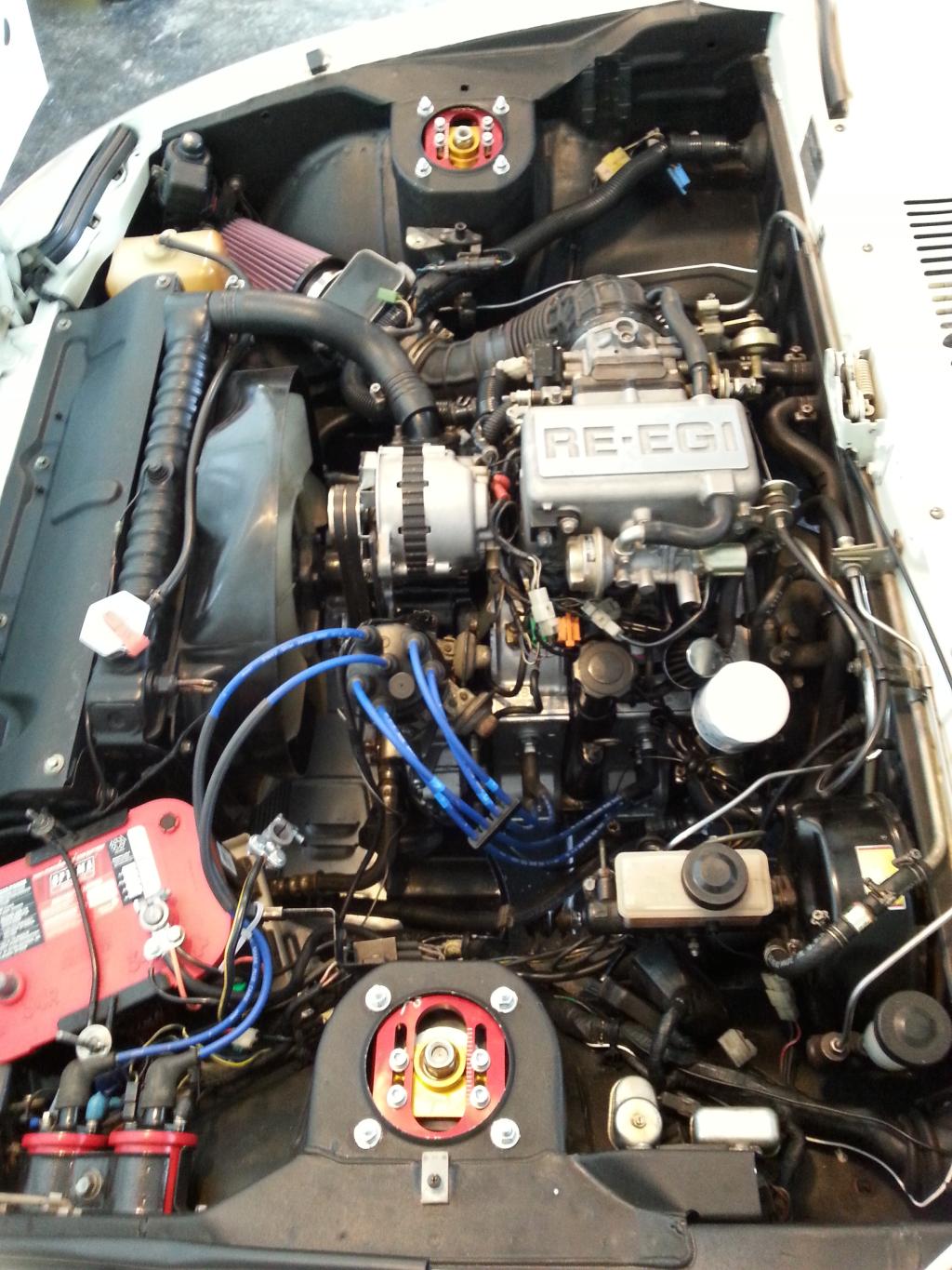
Engine is in!
I still need to hook up the starter, change the coolant gauge sensor connector to a bullet style one (from a 80 to 85 style), get a cone filter adapter for the AFM, the variable resister is in the mail, clearance the fan shroud a bit, fill up with oil and coolant, and get the fuel system and exhaust situated.
I still need to hook up the starter, change the coolant gauge sensor connector to a bullet style one (from a 80 to 85 style), get a cone filter adapter for the AFM, the variable resister is in the mail, clearance the fan shroud a bit, fill up with oil and coolant, and get the fuel system and exhaust situated.
02-22-15, 12:33 PM
#108
Moderator
iTrader: (3)
Join Date: Mar 2001
Location: https://www2.mazda.com/en/100th/
Posts: 30,829
Received 2,597 Likes
on
1,845 Posts
nice, you get bonus points for using the factory hose clamps!
 02-24-15, 11:49 PM
#110
I installed the aftermarket wormscrew type on mine today. They are used hoses and still have the wonderful original wire type imprints. Or, the lower one is. The upper looks like a newer OEM replacement which always had a wormscrew type on it. They don't leak a drop.
I think I might have a set of original wire type somewhere in the pile.
I think I might have a set of original wire type somewhere in the pile.
02-25-15, 01:06 AM
#113
Oh I even used a couple of squeeze style clamps on the lower heater core hose
fitting from the rad to the steel tube running along the firewall. You know the
one. The hose and the squeeze clamps came from an FD, apparently. So, I guess
the CYM color the PO painted in the engine bay is still ok?
fitting from the rad to the steel tube running along the firewall. You know the
one. The hose and the squeeze clamps came from an FD, apparently. So, I guess
the CYM color the PO painted in the engine bay is still ok?
02-26-15, 06:32 PM
#114
Engine is done! Oil system primed, air filter done (Until I do a s4 or s5 UIM swap...maybe). All it needs to run is the fuel tank and header. Just for the heck of it I sprayed some starting fluid in the BAC hose and ran it a few times with open manifold to hear it growl!


 03-12-15, 09:55 PM
#115
Its almost there! I got the airtex e8000 mocked up for testing purposes. Since i dont have a fuel tank im running the inlet and return into a 2 gallon lawnmower jug. At first I got nothing, but then I noticed that I was missing a connection while studying the wiring diagram. The BR wire coming from the cirvuit opening relay connects to the ECU, but also connects to the ignition START switch. So i jumpered the 12v from the circuit opening relay from the fuel pump 12v over to the BR wire and bam! It sputters now. So as the night grew late i cleaned up and called it a day. So im thinking the timing is off and the dizzy needs to be restabbed.
03-17-15, 02:20 PM
#116
Moderator
iTrader: (3)
Join Date: Mar 2001
Location: https://www2.mazda.com/en/100th/
Posts: 30,829
Received 2,597 Likes
on
1,845 Posts
the fuel pump works like the FC, the circuit opening relay has two triggers, the ECU; when it gets rpm signal, and the "start" pin on the ignition switch
03-17-15, 06:42 PM
#117
I got my SE dash/engine bay harness in today and got it all unloomed and cleaned up. I adapted the needed circuits into the SA chasis and taped and loomed it. I also go my new 13b RB header from Racing Beat. Jim was nice enough to give me a foot of scrap pipe and flanges to make a 7 inch connecting pipe to make up for the SE header being shorter than the SAs. I have it all mocked up and ready to be dropped off at the welder, but in the mean time Ive been running the car open header
03-17-15, 06:45 PM
#118
For future SE swapers here is my wiring modification list...
-RW gets 12v power from the MAIN relay
-L wire from the CIRCUIT OPENING RELAY goes to the stock fuel pump wire near the emissions box for 12v power to the fuel pump ,drivers foot panel (this will be used to trigger a relay when I get my internal surge tank from Elwood. A fresh 12V wire will be ran from the battery to supply power to the IST lift pump and main pump)
-BW wire gets 12v power straight from the battery and supplies everything with 12v power via the CIRCUIT OPENING RELAY
-Thick BR wire gets power from the IGN START switch (BY wire under steering column on SA, basically the same wire connected to the starters spade terminal) It supplies signal to the CIRCUIT OPENING RELAY and ECU.
-Two B with brown dots wires get grounded to the chasis.
-One thick BY wire goes from the 6 pin connector under the washer bottle to the + terminal of each coil.
-One shielded Gy wire goes from the 6 pin connector under the washer bottle to the - terminal of the TRAILING coil.
- The exposed portion of the shielded wire for TRAILING signal gets grounded to the passenger strut tower.
DONE!
To help clean up the new circuits coming off of the battery I plan on installing a FC fuse block. I have added 2 small fuse holders for the ECU and CD player recently and plan on running a new line for the fuel pumps so I will need a cleaner alternative than just adding blade fuses everywhere.


 03-27-15, 08:53 AM
#123
Thanks for the compliments. The garage is a blessing, although i wish i had more room! No seen is the other half of the garage which stores my wifes car, three 12as, a John Deere rider, water heater, parts washer, engine hoist etc. Im **** retentive so everything has to go in a specific spot and i clean up after every project.
The car is done minus plumbing the fuel pump in. Im stumped on this Airtex E8000. Odd connections are making it a challenge.
ElwOods handywork came in a couple days ago. The IST is definately the best way to go. I just have to get the fuel line plumbed and it will be ready to drive.
I will need to adapt 8an to 1/2 barb to filter to pump inlet. Then adapt 6an to 3/8 barb to return hard line.
But... the pump outlet to main supply hard line is a PITA. Pump is a wierd m12 1.0 threaded banjo type stud. It will probably have to be retapped to a 1/2" npt so i can run a 5/16 barb adapter.
Last edited by NCross; 03-28-15 at 08:26 AM.
03-28-15, 09:15 AM
#124
Well i figured out a solution to the problem. I just unscrewed the 18mm threaded bit of the airtex pump. I drilled and tapped it to a 5/16x18 sae thread and stuck a 5/16" npt barb in there.
My only concern is that in the process i had to remove what looks like a needle seat with rubber cap and spring. I hope it doesnt cause any issues.
My only concern is that in the process i had to remove what looks like a needle seat with rubber cap and spring. I hope it doesnt cause any issues.
Last edited by NCross; 03-28-15 at 09:51 AM.
03-31-15, 10:47 PM
#125
Got the IST and tank installed. Here is the first run video. Drove her around neighborhood a few times! Lots of power and very smooth. My lumpy idle and backfire problem has gotten better but is still present. Seems like maybe a drippy injector or maybe the dizzy is fubar. Its a 12A dizzy. Is the timing curve and leaky injector causing the backfire and "mini bridgeport" idle? Seems to be running super eye watering rich too.
Last edited by NCross; 03-31-15 at 10:50 PM.