When you click on links to various merchants on this site and make a purchase, this can result in this site earning a commission. Affiliate programs and affiliations include, but are not limited to, the eBay Partner Network.
It’s been a very busy few weeks since I got the harness. Many a DT/DT/DTP connectors has been crimped like a large grandmother hugging the breath outta her beloved horde of grandchildren. Truly yeoman’s work. But alas, those weeks of work will not be self-evident in the pictures below… certainly not to the uninitiated to motorsports wiring. So for those neophytes seeking accession into that realm, I first offer a precious gift: Motorsports ECU Wiring Harness Construction (rbracing-rsr.com)
Like all motivating project, this one begins with an objective… simply install the new ECU harness and accessories. Ok, easy ‘nuf.
I built it some � century ago so it should be easy… right? But wait, what the hell is this wire… and this wire, and this one, and why did that Navy nugget put those there when the car was first wired? And what was I thinking with all of these relays to critical components? What a foolish hack I must’ve been. But now that I think about it, hell, 25 years ago couldn’t have even found a Deutsch connector to save my life… what a wiring Neanderthal I must've been?!?
<Enter stage right, the omni-present Time Succubus of Project Creep... speaking in a French voice> Sacr� bleu mon amie, DO LET the good be the enemy of the perfect!!
And so it begins, deliciously tempted by the franco-demon… the first shot in the unintended and unholy Wire Wars is fired!
Like any good tactician and strategist, the first order is to prepare the battlefield. Every wire must be accounted for, identified and properly labeled. And that in turn requires recreating all of the wiring schematics. OK, so it’ll be a protracted but winnable engagement. <a weekend or two armed with the label maker and heatgun passes>
Next, the electrical beachhead to tackle the firewall pass-throughs needs to won. A two-part, pincer movement is chosen: the main ECU harness and a separate accessories harness will each get their own breakthroughs. The ECU harness firewall mount is manufactured and installed in the OEM ECU hole. Bang. Cut. Epoxy. Rivet. Bang. It’s done. The secondary firewall pass-through makes tactical sense for the (3) EGTs, ground shielding, and the 20A Spal thermo fan… with a reserve of future expandability. An old (ECU leftover) Deutsch HDP-26-24 connector-pair gives me the connector ‘high ground’ thanks to its variety of 20-12 AWG pins and manageable size. Now where to put it? Don’t want to cut a new hole in the firewall. Needs to be on the driver side. Then I see the clear shot: an original heater pass-through can be repurpose with a little expansion. This begets the inexorable need for a new tool. JOY!! One that can cleanly cut a hole, but without requiring the center drilling of a hole saw. Here, my allies in the plumbing industry come through with the perfect ordnance … an ‘merica-made Greenlee knockout tool and die set. As luck would have it, even in the perfect size for the Deutsch connector. Huzzah! the fog of war is kind… this time!
Greenlee Knockout tool and die set
Greenlee Knockout and HDP Connector size confirmation
Greenlee Knockout cutting from cabin
Greenlee Knockout cutting from engine
Firewall hole
Deutsch HDP26-24 (unpinned) Installed
Fuse Sub-panel
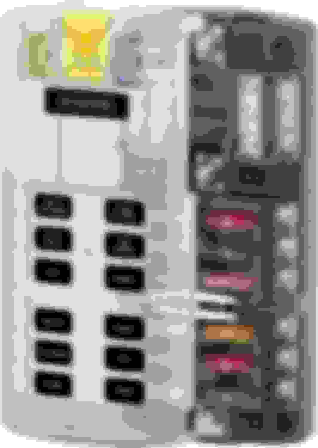
The next campaign is the elimination of a brigade of critical circuit relays. While the nuclear option of a PDM is seriously considered, the time-money collateral damage is deemed still too great. However, it is the inescapable future. Just not now. So more conventional means become the plan. The front is drawn at the fuse sub-panel. It will require another bifurcated pincer tactic: a switched and constant battery voltage circuit approach. While my antiquated setup used some Maginot Line sized circuit breaker blocks from the ’90 car audio, the new setup had to me more elegant. Fuse sub-panel circa 2004
The first ‘hill’ to be taken overcoming the fact that several of the sub-panel fused circuit were >30amp, which is the ATC/ATO blade fuse size limit. While this, I would use many of the compact fuse subpanel. Thankfully, I remember that many of the sub-circuits had been removed (e.g. heaters, defrosters, wipers, stereo, et.) or given their one dedicated fused circuits (i.e. fuel pumps, ECU, and headlights). So a few hours tracing the remaining required circuits in the FSM's pages Z-23 – Z105 schematics showed that I affirmed that ALL circuits (e.g. B1, B2, BTN, et) could in fact be power within ATC/ATO fuses amperage. Some even as low as 15 amps. This vastly opened up what the sub-panel options. With this advantage, the goal became a circuit sub-panel that was mid-size (10-16 sub-circuit), AND was split into two circuit groups; I needed a +12v constant group and a +12v switch group. A call to the intel (i.e. Google) and both Bussman and Blue Sea options came to the fore. Since this would not be a long-term solution (vice a PDM), the Blue Sea 5032 was quickly airdrop into the AOR.
The +12v constant wire was simple. However to wire the +12v switched was not going to go down without a design fight. Its biggest gun was the need for a relay that could handle at least 80 amp with some overhead. Back to ‘intel’ for support. This time, my decades long wiring ally at Ballenger Motorsports engaged with a “75A” TE relay (rate at 135A @ 85�C) that could easily win the current fight.
All of wiring was tidied up with labels, heatshrink, sheathing, and wraps, and the valor medals and ribbons and celebrations of the victory was enjoyed.
Blue Sea fuse sub-panel and battery (cover off)
But alas, the revelry was fleeting for there is still a Wiring War to win…
Last edited by Carlos Iglesias; 11-12-21 at 05:50 AM.
Reason: ADD
I wasn't satisfied with the original injector sub-harness. I had nicked two of the wires at the injector connectors while fixing an inevitable case of ADD dumb-assness. Coincidentally, I wasn't specific on the new engine harness termination, so I got a Deutsch DT-8 on it with the four signal wires and four matching power wires. Since my old setup was a DTM-6 (one 18 gauge branched out in the harness and four signal wires) I took the opportunity have a go at a new one. Well I'm quite pleased with myself.
There is a common tension between fuel pump flow capacity and fuel heating. Large pumps flow torrents, but also cook the fuel relative to bypass flow (especially at higher pressure). Small pump impart less heat, but dribble. Of course, ceteris paribus. In a particularly heinous setup, my previous triple 044 flow-throughs setup (one lift and two in parallel pressure) was a thermal and current cooker. So I took a crack at doing better with this setup. As is always the case with good design, first a little learning... from no finer hydrocarbon Aristotle than my old friend Paul Yaw.
...Well ****, his PRI lecture on Fuel Flow troubleshooting is THE best video but it's no where to be found. It shared some crazy insights including regulator and fuel harmonics troubleshooting, fuel pump dynamics, and much more. Guess I'll ask him what he did with the video next time we shoot the ****; I'll then post it here. Anyways, the salient insights were:
Flow-through (fluid cooled) pumps (all oems, and just about everything else) transfer substantially more heat to the fuel that ones with the motor isolated from the actual pump (Weldon, Magnaflow, et).
Fuel heating has three source: pump cooling, fuel rail heating, and bypass recycling (return systems).
Pump Cooling is a design issue; buy the right pump.
Fuel Rail heating is relatively small, but can be mitigated.
Bypass recycling is related to pump size relative to injector flow; minimize. bypass flow while feeding ample rail volume
Higher rail pressure (base + boost signal) = more thermal energy imparted
So now my Walbro lift pump is a still flow-through and my main pump is Weldon (none flow-through) . While my lift pump will free flow (<1psi), the main pump will have a base pressure of 3 Bar. These are necessary packaging and atomization evils. So back to the bypass heat, that is mitigated by running just enough fuel flow through both pumps to only bypass ~10% at any flow demand. So how will I conjures such alchemy: solidstate PWM control.
The pumps will be individually PWM controlled via respective ECU 2-D maps. The signal feeds a RaceGrade SSD-P at 10KHZ. Flow will be proportional to duty cycle. Presto magico...a Goldilocks-sized Fuel Flow! And it looks like this...
Last edited by Carlos Iglesias; 11-14-21 at 08:42 AM.
Reason: ADD
I'm finishing up the engine /EFI electrical work. One of the design objectives was to have firewall harness disconnects so I could simply unplug a couple Autosport/Deutsch connectors and pull the entire engine with the harnesses still installed. Easy breezy, right?!?! But like the Rube Goldburg design that I'm so prone to, an interesting part of this was incorporating the EGT thermocouples (TC) across the interconnects. You see, TC can't have any junctions made up of anything but the specific metal (i.e. Alumel or Chromel) for each wire. No normal nickel steel connector which would act as a cold junction, destroying accuracy. I found the solution in specific Deutsch DTM pins/sockets. But admittedly, I was somewhat surprised by the cost.... especially given their uber-teeny weeny-ness. Actually the more I thought about it, the more remarkable the cost seemed. I eventually concluded that they were in fact, unobtanium-priced: a 0.2517gm Alumel/Chromel pin cost about $23. If I get out the abacus... that a whopping the $2590/oz. The spot price of Platinum is ~$1000/oz and gold $1791/oz. If that ain't unobtanium, then I don't know what is.
'nuf said.
Will have quite a few more updates this weekend.
Last edited by Carlos Iglesias; 11-26-21 at 07:49 PM.
A really good question... and underlying solution. For lack of creativity, I frankly never considered it. However, if I had, I still would have gone the same route I did. My tongue-in-cheek cost comments about the pins aside, there wouldn't have been any actual cost advantage for me to use the amplifier. Perhaps more importantly, I like to design simplicity of not adding another box to the system... much less in the engine bay. That said, I also was already incorporating a passthrough connector with plenty of room, so none of these additional costs applied. Few would have this luxury, so your solution would make a lot more sense for most setups given the connector/pin/tooling costs of my solution.
Finished the engine harnesses. The LMS-EFI Autosport terminated harness is the main EFI harness. Having made (or should I say 'hacked') harnesses before, the craftsmanship, flexibility, and tidiness of Chris's concentrically wound cable is deeply appreciated. If there is any doubt, compare it to my Deutsch HDP monstrosity... it embarrasses it DR-25 sheaved neighbor.
One addition tweak was that the current arrangement allowed repositioning braided brakeline to a less obtrusive location. However, this too is temporary as it will be improved with a nicely tucked hardline in the next iteration. Like everything, a step forward causes an unintended 1/2 step backwards... now I just need to do something about the old mounting holes...
Engine EFI harnesses overview
Deutsch HDP26-24-29:
Thermocouples EGT1 & WGT2 (20AWG x 2)
Thermocouple common shield ground (15AWG)
Tranny Neutral switch (16AWG)
Tranny Neutral switch (16AWG)
Tranny 1st Gear switch (16AWG)
Tranny 2nd Gear switch (16AWG)
Tranny Reverse switch (16AWG)
Tranny Speedo (16AWG x2)
Thermo Fan power / ground (12AWG x2)
Deutsch HDP connector Deutsch HDP connector
Autosport and HDP connectors
Last edited by Carlos Iglesias; 11-28-21 at 10:54 AM.
Reason: ADD
In your application using chromel and alumel pins looks essential. What you lose by not using them is that the temperature differential across the wiring / connector that isn't thermocouple wire / pins is not measured. In your case this would be the pass through connecter, and there is likely to be a pretty big temperature difference across this with things right by the turbo.
Finished the interior cornerstones. Electronics. Paint.
I'm trying VERY hard to make my existing marriage to the stock harnesses work... but by God, she is untidy and capricious! I suspect we do not have a future together at this point.
Life's hard... but it's harder when you're stupid!!
Finally ran a compression check on the post-build, pre-startup engine. At 273 RPM (add 7% to below to normalize to 250 RPM OEM standard) in psi:
Front - 94/103/124
Rear - 134/131/136
This is an ALL-NEW engine (minus Mandeville-massaged rotors and e-shaft) that has not been started. While my reaction is to tear it back down to fix the front rotor compression, my good friend put me on the fence with his recommendation to just start it up and see if the compression improves. I'm still mulling it over. Thankfully it's not holding me back since I just got yesterday my initial maps from ShaneT and I need to test all of the inputs & outputs... with the expectation of some troubleshooting my work there as well. Time will tell... as it tyrannically always does.
Never let the Perfect be the enemy of the Good - some pansy *** French dude.
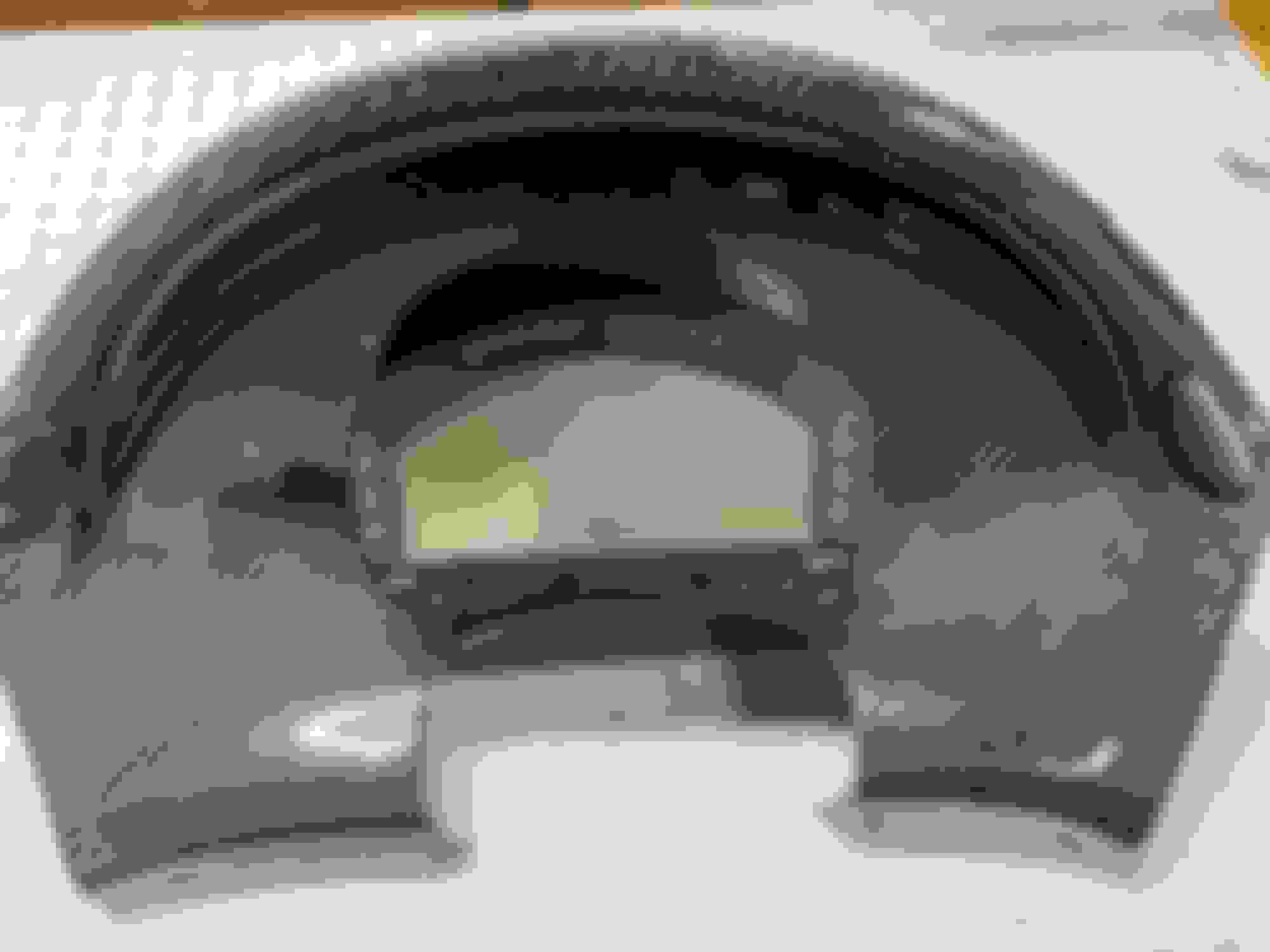
Waiting on my hot date with a 'well-endowed' tuner, I decided to finally give my decade old Aim MXL dash a proper mount (even if it looks a little lonely). Now that I can display everything I need on it thanks to the M1's extensive CAN broadcast, I'm planning to leave it as the lone display/gauge...at least until I upgrade to a C127 or AIM PDM32. The low positioning accounts for that intention, as well as better visibility.
Last edited by Carlos Iglesias; 12-18-21 at 08:39 AM.
Reason: ADD
Would you mind sharing the backside of your MXL dash mounting solution?
I am working with my friends in NJ on trying to find a solve for the curvature of a blank Evo-R dash (is that what you have here?) and an MXG for a flush, clean, but most importantly solid mount
I have gone international (AiM UK, AiM East Coast, draklore, FD3RS, Maxwell Manufacturing, Mako Motorsport, oldschool looks at GrandMighty) drawing at straws on a solution for something comparable here that I think shouldn't be rocket surgery, so would appreciate a view at your take
I think my buddy Brian has something here, but the more solutioning I can do the better!
Would you mind sharing the backside of your MXL dash mounting solution?
Too easy, I'll get pictures and the template I used for the install. Unfortunately though, I'll need to string you out until tomorrow... look at it as an early Christmas gift.
The AIM dash is mount to the instrument panel with M4x10mm isolation standoffs / mounts. The mounts are held to the hood by M4 fasteners, stainless and nylon washers. The nylon washers give a slightly more pliable mount against the CF.
Depending on the installed final viewing angle, I may get a slightly long isolation mount in the bottom pair of holes to angle the piece slightly more upward.
Feliz Navidad!!
Last edited by Carlos Iglesias; 12-25-21 at 10:06 AM.
Reason: ADD
 10-02-21, 09:47 AM


 .
.


