Aquamist HFS-5 system: Official Q&A...
 09-16-08, 09:23 PM
#101
Hi Richard, I just sent you a PM asking a couple of questions regarding the Aquamist 2d.
And regarding the name of the Summer in England, don't you guys have lots of fog in London? It could be called Fogger
Leo
And regarding the name of the Summer in England, don't you guys have lots of fog in London? It could be called Fogger
Leo
 09-17-08, 09:56 AM
#103
Full Member
iTrader: (1)

Join Date: Feb 2007
Location: Lancashire Uk
Posts: 62
Likes: 0
Received 0 Likes
on
0 Posts
ok sort of related, sort of thread hijack, so sorry in advance!
I need to run a second HSV with its own FIA, does anyone know what else i would need- i am presuming that the DDS3 system isnt required, but can i shortthe grey trigger wire to activate the FIA2? looking at the diag, i should be able to splice in another flow sensor to the FIA2, and this should give blocked jet warning- is this correct? so by my reckoning i need HSV,FIA2, flow sensor and associated piping. anything i have missed?
I need to run a second HSV with its own FIA, does anyone know what else i would need- i am presuming that the DDS3 system isnt required, but can i shortthe grey trigger wire to activate the FIA2? looking at the diag, i should be able to splice in another flow sensor to the FIA2, and this should give blocked jet warning- is this correct? so by my reckoning i need HSV,FIA2, flow sensor and associated piping. anything i have missed?
09-18-08, 06:13 AM
#105
Full Member
iTrader: (1)
Join Date: Feb 2007
Location: Lancashire Uk
Posts: 62
Likes: 0
Received 0 Likes
on
0 Posts
richard i sent you a couple of emails regarding this, I currently have a HFS5 kit that is in the process of being fitted, but want to drive one HSV from the primaries, and one from the secondaries. as they would be running in parrallel i would need two flow meters, but dont want to go down the complexity (and expense) of running two DDS3 systems.
Last edited by marco137; 09-18-08 at 06:17 AM. Reason: spilling mistacks
09-28-08, 05:43 AM
#106
Senior Member
Thread Starter

Join Date: Sep 2006
Location: uk
Posts: 402
Likes: 0
Received 0 Likes
on
0 Posts
Marco137,
I still think we can achieve this without having to doubel up everything. What about have user adjustable two trip points based on the output from the summer?
Monitoring the fuel % gives a very consistant account of your power level regardless of RPM, boost or gearing.
What do you think?
I still think we can achieve this without having to doubel up everything. What about have user adjustable two trip points based on the output from the summer?
Monitoring the fuel % gives a very consistant account of your power level regardless of RPM, boost or gearing.
What do you think?
09-29-08, 03:33 AM
#107
Full Member
iTrader: (1)
Join Date: Feb 2007
Location: Lancashire Uk
Posts: 62
Likes: 0
Received 0 Likes
on
0 Posts
Richard,
The problem is that I want to inject preturbo whilst running sequential. As such the control of the HSVs has to be separate- yet still tied into the amount of fuel. in effect what I am looking to do is have X% fuel/water ratio, but below a certain threshold have all the water being controlled by one hsv, and above the threshold have the amount of water split, and be controlled by the second. For example if we assume 3500rpm,
Below 3500 rpm 15% (of fuel) water through HSV1
Above 3500 rpm, 7.5% water through HSV1, and 7.5% through HSV2.
So unless the summer could split the duty cycle like this, I can�t see how it would work. The ideal solution would be to have a controller that could run two independent PWM maps simultaneously; I don�t think yours can do that can it?
Which is why I was thinking of using the primary and secondary injectors- the total amount of fuel is controlled by the ecu, and above a set duty cycle on the primaries, the secondaries kick in. so I have the separation of duty cycles that I need! However it will need a lot of fettling with regard to injector sizes (both fuel and water) and getting the switch over point right, but I still think it is a viable solution
marco
09-29-08, 03:53 AM
#108
Senior Member
Join Date: Nov 2004
Location: England
Posts: 383
Likes: 0
Received 0 Likes
on
0 Posts
careful Marco I think you are trying to over complicate your proposed setup, do one or the other (pre or post turbo)
Also at 3500rpm I think its too early to inject personally, what turbo do you run and what porting?
Also at 3500rpm I think its too early to inject personally, what turbo do you run and what porting?
Last edited by blitzboy; 09-29-08 at 03:58 AM.
09-29-08, 04:45 AM
#110
Full Member
Join Date: Oct 2001
Location: Manchester, England
Posts: 156
Likes: 0
Received 0 Likes
on
0 Posts
Richard,
A quick question. I'm taking my car in for mapping this weekend and could do with setting up logging on the Summer beforehand. What are the parameters I need for 0v and 5v to get the correct readings from the water flow sensor?
thanks,
Steve
A quick question. I'm taking my car in for mapping this weekend and could do with setting up logging on the Summer beforehand. What are the parameters I need for 0v and 5v to get the correct readings from the water flow sensor?
thanks,
Steve
09-29-08, 05:16 AM
#111
Senior Member
Thread Starter
Join Date: Sep 2006
Location: uk
Posts: 402
Likes: 0
Received 0 Likes
on
0 Posts
Richard,
The problem is that I want to inject preturbo whilst running sequential. As such the control of the HSVs has to be separate- yet still tied into the amount of fuel. in effect what I am looking to do is have X% fuel/water ratio, but below a certain threshold have all the water being controlled by one hsv, and above the threshold have the amount of water split, and be controlled by the second. For example if we assume 3500rpm,
Below 3500 rpm 15% (of fuel) water through HSV1
Above 3500 rpm, 7.5% water through HSV1, and 7.5% through HSV2.
So unless the summer could split the duty cycle like this, I can�t see how it would work. The ideal solution would be to have a controller that could run two independent PWM maps simultaneously; I don�t think yours can do that can it?
Which is why I was thinking of using the primary and secondary injectors- the total amount of fuel is controlled by the ecu, and above a set duty cycle on the primaries, the secondaries kick in. so I have the separation of duty cycles that I need! However it will need a lot of fettling with regard to injector sizes (both fuel and water) and getting the switch over point right, but I still think it is a viable solution
marco
All you need to do is select a suitable point to open up those valves to perform the pre-turbo work.
Those valve will be fed from the outlet of the HSV. The HSV can deliver over 1500cc/min.
Next step will be We finding an appropriate signal to trigger those MSVs. I can help you fabricating a controller when necessary. Monitoring the primiary or secondary wastergate control valves signal or just the onset of the primiary and secondary fuel injectors (user adjustable of course).
09-30-08, 06:16 PM
#112
Senior Member
Thread Starter
Join Date: Sep 2006
Location: uk
Posts: 402
Likes: 0
Received 0 Likes
on
0 Posts
Please use 0-5V input for all logging parameters.
10-01-08, 04:13 AM
#113
Full Member
Join Date: Oct 2001
Location: Manchester, England
Posts: 156
Likes: 0
Received 0 Likes
on
0 Posts
Thanks Richard, that's what I'm using. I need to know what 5v equals in cc though. When powered up I'm reading 0.5v with no flow so can put that in on my logger: 0.5v = 0cc
I then need to add 5v = ?cc
From memory the label on the flow sensor reads 4.5v = 420cc but the Shurflo pump flows more than that easily so I'm assuming that's an out of date spec?
Steve
I then need to add 5v = ?cc
From memory the label on the flow sensor reads 4.5v = 420cc but the Shurflo pump flows more than that easily so I'm assuming that's an out of date spec?
Steve
Last edited by efiniste; 10-01-08 at 04:26 AM. Reason: wrong pump!
10-01-08, 04:39 PM
#114
Full Member
iTrader: (1)
Join Date: Feb 2007
Location: Lancashire Uk
Posts: 62
Likes: 0
Received 0 Likes
on
0 Posts
Richard,
forgive me if I got the wrong end of the stick, but I was under the impression that the amount of water discharged was dependant on the nozzles used? so if I have a secondary valve then when it opens it will increase the total flow rate, and so the water/fuel ratio will be thrown? Or can the flow be choked upstream of the nozzles so that total flow is maintained regardless of the number of nozzles downstream? And if this is the case would the switching in of a seocnd nozzle reduce the pressure in the line and impair the atomization?
What cost am i going to be looking at for a HSV and an FIA(or summer) set up? i had guessed it would be below �200, which in my mind is a fair price. I think by the time i have put in a MSV and built control logic for it (and accounting for my time) it will come to something similar! I think it would be better if we continued this over a phonecall, do you have a number I can use to contact you?
10-01-08, 05:38 PM
#115
Senior Member
Thread Starter
Join Date: Sep 2006
Location: uk
Posts: 402
Likes: 0
Received 0 Likes
on
0 Posts
logging the Aquamist Summer
Thanks Richard, that's what I'm using. I need to know what 5v equals in cc though. When powered up I'm reading 0.5v with no flow so can put that in on my logger: 0.5v = 0cc
I then need to add 5v = ?cc
From memory the label on the flow sensor reads 4.5v = 420cc but the Shurflo pump flows more than that easily so I'm assuming that's an out of date spec?
Steve
I then need to add 5v = ?cc
From memory the label on the flow sensor reads 4.5v = 420cc but the Shurflo pump flows more than that easily so I'm assuming that's an out of date spec?
Steve
The flow sensor's output is 0.5V to 4.5V. Flow detection range is between 100-2000cc/min.
Due to the wide operating range, we introduced a "scaling" input so that the sensor can be retained the same 0-5V output at a smaller flow.
Your gauge has this scaling potentiometer called "SC". I am certain you have already calibrated this for your failsafe window agaibst your current flwo range. I advise you to leave this alone.
As regarding setting your 0-5V logging multiplier, it will depend on your current maximum fluid flow through your jet under boost. Let say you are using a 500cc/min jet, displaying 5 bars on the gauge.
Since full 8 bars displayed on the gauge is equvalent to 4.5V. So 5 bars = 2.8v or 500cc/min.
Based on above example, your logger mulituplier should be set to: 178.57cc/Volt.
10-01-08, 05:56 PM
#117
Senior Member
Thread Starter
Join Date: Sep 2006
Location: uk
Posts: 402
Likes: 0
Received 0 Likes
on
0 Posts
Richard,
forgive me if I got the wrong end of the stick, but I was under the impression that the amount of water discharged was dependant on the nozzles used? so if I have a secondary valve then when it opens it will increase the total flow rate, and so the water/fuel ratio will be thrown? Or can the flow be choked upstream of the nozzles so that total flow is maintained regardless of the number of nozzles downstream? And if this is the case would the switching in of a seocnd nozzle reduce the pressure in the line and impair the atomization?
What cost am i going to be looking at for a HSV and an FIA(or summer) set up? i had guessed it would be below �200, which in my mind is a fair price. I think by the time i have put in a MSV and built control logic for it (and accounting for my time) it will come to something similar! I think it would be better if we continued this over a phonecall, do you have a number I can use to contact you?
forgive me if I got the wrong end of the stick, but I was under the impression that the amount of water discharged was dependant on the nozzles used? so if I have a secondary valve then when it opens it will increase the total flow rate, and so the water/fuel ratio will be thrown? Or can the flow be choked upstream of the nozzles so that total flow is maintained regardless of the number of nozzles downstream? And if this is the case would the switching in of a seocnd nozzle reduce the pressure in the line and impair the atomization?
What cost am i going to be looking at for a HSV and an FIA(or summer) set up? i had guessed it would be below �200, which in my mind is a fair price. I think by the time i have put in a MSV and built control logic for it (and accounting for my time) it will come to something similar! I think it would be better if we continued this over a phonecall, do you have a number I can use to contact you?
You are absolutely correct, although the HFS-5 mirrors the fuel injector, throwing in an extra nozzle midway will alter that ratio for sure.
The HFS-5 pump can maintain 125psi of water pressure in excess of 2000cc/minute. So you don't have to worry about the pressure drop until you are running multiple jets, totalling beyond of 2000cc/min.
I guess the only way to achieve a fixed water/fuel ratio is using two HFS-5 and two summers. We can discuss this over the phone. By then I might be able to figure out an alternative method costing less.
I should be in the office tomorrow, If not you will gaive you an alternative phone where you can reach me on.
Richard
10-01-08, 06:43 PM
#118
Full Member
Join Date: Oct 2001
Location: Manchester, England
Posts: 156
Likes: 0
Received 0 Likes
on
0 Posts
The answer is 5V = ?cc/min is dependant on the "scaling" potentiometer (SC).
The flow sensor's output is 0.5V to 4.5V. Flow detection range is between 100-2000cc/min.
Due to the wide operating range, we introduced a "scaling" input so that the sensor can be retained the same 0-5V output at a smaller flow.
Your gauge has this scaling potentiometer called "SC". I am certain you have already calibrated this for your failsafe window agaibst your current flwo range. I advise you to leave this alone.
As regarding setting your 0-5V logging multiplier, it will depend on your current maximum fluid flow through your jet under boost. Let say you are using a 500cc/min jet, displaying 5 bars on the gauge.
Since full 8 bars displayed on the gauge is equvalent to 4.5V. So 5 bars = 2.8v or 500cc/min.
Based on above example, your logger mulituplier should be set to: 178.57cc/Volt.
Ah, I didn't realise the SC pot affected it. Makes sense now, thanks Richard.
10-02-08, 10:13 AM
#119
Senior Member
Thread Starter
Join Date: Sep 2006
Location: uk
Posts: 402
Likes: 0
Received 0 Likes
on
0 Posts
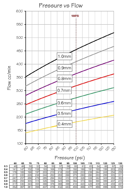
If possible please email me the logged chart or post them here.
I have not yet seen any chart since the Summer was released. Don't forget to insert the restrictor so that the flow will be linear to the IDC.
Here is a chart to help you matching the jet to the restrictor.
I have not yet seen any chart since the Summer was released. Don't forget to insert the restrictor so that the flow will be linear to the IDC.
Here is a chart to help you matching the jet to the restrictor.
10-06-08, 06:27 AM
#122
Full Member
Join Date: Oct 2001
Location: Manchester, England
Posts: 156
Likes: 0
Received 0 Likes
on
0 Posts
Steve
10-08-08, 02:43 AM
#125
Full Member
Join Date: Oct 2001
Location: Manchester, England
Posts: 156
Likes: 0
Received 0 Likes
on
0 Posts