
Wiring Mod For Hotter Ignition

development
Joined: Aug 2002
Posts: 5,714
Likes: 7
From: Lafayette, LA
no, Chuck's master plan is flawless...his routing explanation was flawed (at least the way I read it)
All the info you'll need and more...
ECU Pins (F) Front harness
1J - BR/B = Trailing Rear
1G - BR = Trailing Front
1H - LG = Leanding
Ignitor Outputs (F) & (E) Emission harness
LG/W - Trailing Rear
LG/R - Trailing Front
LG/B - Leading
B/W on ignitor is IGN 12V
Coil Wiring (IG) Ignition harness
L/W - Trailing Rear
R - Trailing Front
Y/L - Leading
B/R on coils is IGN 12V
Wire Color Key
BR = brown
W = white
B = black
R = red
LG = light green
L = Blue
Y = Yellow
*****dubulup is not responsible if your car performs better or worse if you do this mod.

Rotary Enthusiast
Joined: Dec 2001
Posts: 1,252
Likes: 0
From: Sunnyvale, CA
I see, so instead of the claimed 14 feet running around from ignitor to coil, its actually more about 4 feet. Ignitor goes down pink harness near the battery then switch over to the blue harness.
And what we are talkign about here is making it shorter to about 2 feet by wiring directly from ignitor to coils? Correct?
Was this change felt much other than refreshing old wiring with new ones?
thanks
Reza
And what we are talkign about here is making it shorter to about 2 feet by wiring directly from ignitor to coils? Correct?
Was this change felt much other than refreshing old wiring with new ones?
thanks
Reza
Originally Posted by dubulup
Chuck had the right idea, but had the routing a little mixed up. Re-wiring the engine when I installed the Haltech helped edjamacate me 
my ignitor outputs now run along the firewall with the engine harness, and I'm building a short harness that hits the coils direct from the ignitor (with a secret squirrel 12V switch, so I can cut ignition (coils and ignitor) with the flip of a switch in the driver's seat...a thief will never get my car started, even if he had ALL the info in the world about FD's, so shhhhhhhhhhh none of you will be able to find the switch either )
my ignitor outputs now run along the firewall with the engine harness, and I'm building a short harness that hits the coils direct from the ignitor (with a secret squirrel 12V switch, so I can cut ignition (coils and ignitor) with the flip of a switch in the driver's seat...a thief will never get my car started, even if he had ALL the info in the world about FD's, so shhhhhhhhhhh
none of you will be able to find the switch either )
Originally Posted by dubulup
no, Chuck's master plan is flawless...his routing explanation was flawed (at least the way I read it)
All the info you'll need and more...
ECU Pins (F) Front harness
1J - BR/B = Trailing Rear
1G - BR = Trailing Front
1H - LG = Leanding
Ignitor Outputs (F) & (E) Emission harness
LG/W - Trailing Rear
LG/R - Trailing Front
LG/B - Leading
B/W on ignitor is IGN 12V
Coil Wiring (IG) Ignition harness
L/W - Trailing Rear
R - Trailing Front
Y/L - Leading
B/R on coils is IGN 12V
Wire Color Key
BR = brown
W = white
B = black
R = red
LG = light green
L = Blue
Y = Yellow
*****dubulup is not responsible if your car performs better or worse if you do this mod.
All the info you'll need and more...
ECU Pins (F) Front harness
1J - BR/B = Trailing Rear
1G - BR = Trailing Front
1H - LG = Leanding
Ignitor Outputs (F) & (E) Emission harness
LG/W - Trailing Rear
LG/R - Trailing Front
LG/B - Leading
B/W on ignitor is IGN 12V
Coil Wiring (IG) Ignition harness
L/W - Trailing Rear
R - Trailing Front
Y/L - Leading
B/R on coils is IGN 12V
Wire Color Key
BR = brown
W = white
B = black
R = red
LG = light green
L = Blue
Y = Yellow
*****dubulup is not responsible if your car performs better or worse if you do this mod.
Thread Starter
Joined: Feb 2001
Posts: 7,943
Likes: 133
From: In A Disfunctional World
Originally Posted by dubulup
Chuck had the right idea, but had the routing a little mixed up. Re-wiring the engine when I installed the Haltech helped edjamacate me
the switch either )
the switch either
)Later when I stripped a car down, I saw the double back. But then the thread was old and I did not post the new info.

Ok, I just read this as I am having problems with either my ignitor or my leading coil. It is working intermitantly and I am killing plugs. I disconnected the trailing coils and the car shut off. It wasn't even firing the leading coil. I tried to sort it out but had to come home and look at the wiring diagram and search through these threads. In doing so I found this one because I had done the harness mod a long time ago. Looking at the schematic and reading this thread I think some are confused as to how our system works.
Chuck, you dismissed Mad7tst but I think he is correct in his statements. The stock coils receive their positive power direct from the ignition. The ignitor gets pulses from the ECU. The ignitor then uses these pulses to switch the ground legs of the different coils to ground therefore firing each coil. This mod does nothing to beef up the wiring going from the ECU to the ignitor which is where the low voltage signal is. What you have done, is shorten the ground wire to the coils.
The ignitor does not send pos. pulses to the coil. The ignition amp (crane hi-6) can not therefor amplify this signal. What it can do is step up the voltage supplied to the coil from the ign input side and refernce the ground trip signal to ground the coil accordingly much like the ignitor does.
Now I am not saying that by shortening these wires, and beefing them up, you are not improving the system. I am just saying that the system operates as decribed by mad7tst. I think that improving the voltage to the coils by upgrading the wiring to the positive terminal and also upgrading the ground side going to the ignitor, will ensure the maximum amount of voltage available at the primary side of the coil. Much like using large wires to connect your amp or fuel pump.
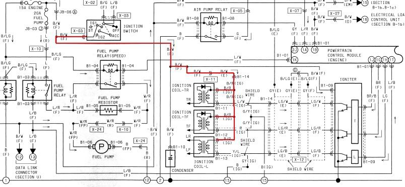
If I am wrong please tell. This was all gathered from the service manual in the wiring section. If you look at dubulup's breakdown of the color codes above. you see that B/W on the ignitor is 12V Pos and B/R on the coils is 12V Pos. If you find these wires in the schematic, they are joined. 12v + is supplied to all 3 coils from a common source. This means that the individual legs (L/W, R, Y/L ON COIL SIDE) and (LG/W, LG/R, LG/B ON THE IGNITOR SIDE) are the trigger wires. If you look at the schematic, you will see that they are shunted to ground at the ignitor.
hope this helps. I am curious now how much voltage is supplied by the crane to the positive side of the coil.
Miike
Chuck, you dismissed Mad7tst but I think he is correct in his statements. The stock coils receive their positive power direct from the ignition. The ignitor gets pulses from the ECU. The ignitor then uses these pulses to switch the ground legs of the different coils to ground therefore firing each coil. This mod does nothing to beef up the wiring going from the ECU to the ignitor which is where the low voltage signal is. What you have done, is shorten the ground wire to the coils.
The ignitor does not send pos. pulses to the coil. The ignition amp (crane hi-6) can not therefor amplify this signal. What it can do is step up the voltage supplied to the coil from the ign input side and refernce the ground trip signal to ground the coil accordingly much like the ignitor does.
Now I am not saying that by shortening these wires, and beefing them up, you are not improving the system. I am just saying that the system operates as decribed by mad7tst. I think that improving the voltage to the coils by upgrading the wiring to the positive terminal and also upgrading the ground side going to the ignitor, will ensure the maximum amount of voltage available at the primary side of the coil. Much like using large wires to connect your amp or fuel pump.
If I am wrong please tell. This was all gathered from the service manual in the wiring section. If you look at dubulup's breakdown of the color codes above. you see that B/W on the ignitor is 12V Pos and B/R on the coils is 12V Pos. If you find these wires in the schematic, they are joined. 12v + is supplied to all 3 coils from a common source. This means that the individual legs (L/W, R, Y/L ON COIL SIDE) and (LG/W, LG/R, LG/B ON THE IGNITOR SIDE) are the trigger wires. If you look at the schematic, you will see that they are shunted to ground at the ignitor.
hope this helps. I am curious now how much voltage is supplied by the crane to the positive side of the coil.
Miike
development
Joined: Aug 2002
Posts: 5,714
Likes: 7
From: Lafayette, LA
Your description of the system is dead on.
however my concern with doing this mod is to shorten the length/resistance the ECU signal has to travel to get to the ignitor. Giving a more accurate timing...and since I'm building a hard zero split ignition, why not simplify things further?
straight from ignition...however I think it could still be shorter, will that make a difference? I don't know...it will eliminate at least 2 connectors will impose more resistance than just wire.
however my concern with doing this mod is to shorten the length/resistance the ECU signal has to travel to get to the ignitor. Giving a more accurate timing...and since I'm building a hard zero split ignition, why not simplify things further?
Originally Posted by crispeed
Due to the design of magnetic/reluctor triggers as rpm increases ignition timing will vary or retard. I'm not going to get into why that happens but do the research and you'll find out for yourself. Most modern ECU's have some type of system built in to remedy that problem. Both the E-8 and 11 ecu series got variable trigger angle vs rpm so basicaly you can eliminate that problem, The previous or earlier 6 series didn't. Timing would retard depending on application up to 10 deg at high rpm. That problem got even worse if gains were increased. Anything placed between the ECU and the coils would aid the problem even further.Everyone's favorite Knock retard and Ignition amplifier box would be prime examples. I've seen up to 10 deg of retard at high rpm. Now for the dangerous part about this whole ordeal would be by placing the metioned above units only on the leading side would result in even more leading ignition high rpm retard than on the trailing side and we all know what that leads to if you're trying to run zero or just a little ignition split again depending on the application, on a heavy load or boosted application. KABOOM!
This is the main reason why the earlier Haltech ecu's were known to fire the trail before the leading when the split got very close. This is not a problem with the latter series once igntion setup is done properly.
You must always verify ignition timing at varied rpm levels for both leading and trailing events.
straight from ignition...however I think it could still be shorter, will that make a difference? I don't know...it will eliminate at least 2 connectors will impose more resistance than just wire.

Rotary Enthusiast
Joined: Jan 2005
Posts: 769
Likes: 0
From: orlando/st. petersburg
Originally Posted by cewrx7r1
RF wires as opposed to DC wires are made to be a fixed impedance no matter how long the wire is. I doubt Mazda used such wiring in our car's ignition system.
. And regardless how much of a difference would this make? probably not noticeable IMO. Wouldnt it be better to replace it with fixed impedance wire instead of shortening the "nonfixed impendance" stock stuff?
Here some new info that I found while trying to fix my non firing leading coil.
1) I was getting voltage at the input to the crane. it was fluctuating around 2.2v with a digital meter.
2) I was getting nothing out of the crane going to the coil. This would imply that the crane HI-6 is not working correctly. The problem is that the reason I put the crane back in was due to the fact that I was fouling the plugs. I now think the problem existed before I through the crane back in. I just didn't realize that I was running on only the trailing plugs. So I went back to tesing the wiring.
3) Testing the voltage at the end of my wiring harness upgrade for the leading coil only yielded once again 2.2v. Testing the voltage at the stock ignition harness where it connects under the throttle body yielded 3.44v or so for the trailing leads which still run stock route. This made me confused as I would have expected better voltage from the shorter wire. I then check to see the resistance of my wire at it had no drop in voltage over the short distance. I then decided to check the voltage for the leading coil directly where the wires come out of the ignitor. The same 2.2v. This confirmes that it was not caused by my new wire.
Now here is the weired thing. I reconnect the ignitor wires back to stock configuration so the signal runs back into the stock ignition harness. I then hook up my meter and check the voltage for the leading coil at the end of the harness in the same way and place that I checked the voltage for the trailing coils. Low and behold the voltage was back up in the 3's like the trailing.
So it would seem that the coil, for what ever reason gets more voltage at the stock harnes than at the ignitor. Maybe the power to the coils is closer/stronger at the ign. harness than at the ignitor.
Anyone else want to test this to verify. Also maybe the best way is to power the coil from the power in the iGn harness but run a new ground to the ignitor. Best of both worlds kind of thing.
I also put a new FC coil in. Everything is working now. I think there was a broken wire near the connector under the insulation that was acting up intermitantly. I am going to play with it more today.
Mike
Last edited by MFilippello; Mar 9, 2006 at 01:19 PM.
any one use a voltage booster like the B&M new volt on just the trailing to increase the power of the stock trailing inductive spark and use CDI on the leading. This would be similar to the HKS twin power but better. You would get a stronger inductive spark on both trailing for all RPM's and a cdi setup on the leading for all rpms. It ould be multi spark under 3000 rpm and single spark above.
Mike
Mike


Thread
Thread Starter
Forum
Replies
Last Post
streetlegal?
New Member RX-7 Technical
13
Mar 17, 2022 02:46 PM
befarrer
Microtech
3
Aug 22, 2015 05:52 PM