
Wiring Mod For Hotter Ignition

Thread Starter
Joined: Feb 2001
Posts: 7,943
Likes: 133
From: In A Disfunctional World
Wiring Mod For Hotter Ignition
Banned. I got OWNED!!!
Joined: Jul 2004
Posts: 1,179
Likes: 1
From: next to the polishing wheel!!!
I have cut the wires near the front of the drivers door under the wheel liner and run them in the hole in the body to the igniter . Doing this simple step rid the system of several feet of wire and the connector in the engine bay .


The big enemy of ignition circuits is noise, and the longer the wiring is, the more noise it can potentially pick up. The signal is relatively weak (low current) and has LOTS of very fast changes - each pulse is a plug firing.
I can see how this would be of benefit, primarily on modified cars. The more power you make, the faster the pulses need to get to the coils. The more accurately you can get the signal to the coils, the better things will be.
Dale
I can see how this would be of benefit, primarily on modified cars. The more power you make, the faster the pulses need to get to the coils. The more accurately you can get the signal to the coils, the better things will be.
Dale
King of the Duct Tape
Joined: Feb 2001
Posts: 1,177
Likes: 0
From: PA
i've never heard this one but it makes sense like everything else i've read from ya chuck. not having the car or manual in front of me my first thought is that it would be great to have pics so as not to cut the wrong wire 
when i dyno'd last i was having a bit of breakup so i'm interested to see how it works. this was with stock ignition and 1bar boost.
when i dyno'd last i was having a bit of breakup so i'm interested to see how it works. this was with stock ignition and 1bar boost.
Trending Topics


http://www.fd3s.net/ignition.html#HAR
It looks like you've known this for a while, Chuck. I'm surprised it hasn't caught on yet.
I understand the theory behind it and why it's better than stock, but has anyone been able to quantify the results? The shorter wiring will be less prone to noise and distortion, especially at higher RPM's. How exactly would you measure ignition breakup, would you use an oscilloscope? Is it something you could see on an AFR readout from a dyno session?
-s-
Lives on the Forum
Joined: Dec 2001
Posts: 14,716
Likes: 10
From: San Lorenzo, California
Originally Posted by mad_7tist
maybe more accurate... but it should not impact the coils output which is how i take hotter to mean
Shortening the leads by half would reduce the power dissipation by half. The question is, is that reduction in power dissipation significant?

Rotary Freak
Joined: Jan 2004
Posts: 1,899
Likes: 0
From: tampa
ok but the disipation is in the signal not the power feed to the coils themselves, unless i read the post wrong. the ecu slaves the ignitor which will allow and remove the ground from the coils. while i think this is an ok idea i just dont see the increase in spark power. if the ignitor fires the coils correctly at 7,000 rpm in stock form the signal should be ok if the car makes 450 hp. if the coils fire is another issue. the coil output is dependent upon the windings, number of turns etc, voltage availability. i will re-read the post but i thought it only had to do with the ignitor firing signal which if it triggers the coil at the right time is doing it's job
mad_7tist: from my understanding, we're talking about the wire between the ignitor and the ignition coils. As far as I know, the coils act as an amplifier, so a more powerful input should yield a more powerful output. Someone please correct me if I'm wrong here. A more important thing would be to ensure that the coils are well-grounded.
Here are some frequency / timing numbers that I worked out. We'll focus on the leading spark as it pertains to one rotor.
The leading plug fires twice per combustion event (research "wasted spark" if you're not already familiar with this). That gives us 6 sparks per revolution of the rotor. The output shaft (flywheel) makes 3 revolutions for every single revolution of the rotor. That gives us (6/3) = 2 sparks per output shaft (flywheel) revolution.
Let's find how many sparks are occurring per second at a given engine speed. (2 sparks / rev) * (xrevs/minute) * (1 minute / 60 sec). You end up with (x / 30) sparks per second. At 8000 RPM's, the leading coil is firing approximately (8000/30) = 266 sparks per second.
Note that the sparks are NOT happening at a perfectly even interval. There should be two sparks in quick succession during the combustion event, with a longer gap between them while the rotor is turning. If we were to represent the spark by a '*' symbol, and the off-time by a '_' symbol, you'd see something like this:
*_*____*_*____*_*____*_*____
Anyway, the important number here is 266 sparks / sec at 8000 RPM, which means absolutely nothing until we have some more info to find out precisely when and why ignition breakup occurs. We would need to find the correlation between voltage (and /or current) at the input to the coil and the strength of the spark created. And then find out how strong of a spark is needed to ignite a certain fuel mixture at a given pressure.
Finding the strength of the spark might involve measuring the resistance of the wire in ohms per foot, but I'd have to do some research to find how much energy will be absorbed by the wires at different engine speeds. Does anyone know the voltage and current seen at these wires?
-s-
Last edited by scotty305; May 20, 2005 at 05:41 PM.
Rotary Freak
Joined: Jan 2004
Posts: 1,899
Likes: 0
From: tampa
that is all assuming break-up has something to do with the coil firing signal. the ignitor just allows and removes the ground to charge the coil and then collapse the field so it sparks. most ignition break-up is tuning, plug type, coil health etc.. related. i have not heard of a documented case of coil signal degredation in a good harness. getting the secondary voltage would not be too hard under load on a dyno with any good scope. prob around 30kv.
Thread Starter
Joined: Feb 2001
Posts: 7,943
Likes: 133
From: In A Disfunctional World
My intent is to inform owners of simple improvements to Mazda's designs. If you studied your car's systems, schematics, and visually checked them out, then you would know more about your car and what I am talking about. But this also requires a good knowledge of mechanics and electonics. These I taught myself from highschool and on, and the USAF also trained me in electronics.
I am not here to teach owners mechanics and electronics.
Either you know or don't.
I am not here to teach owners mechanics and electronics.
Either you know or don't.
Originally Posted by mad_7tist
maybe more accurate... but it should not impact the coils output which is how i take hotter to mean
Rotary Freak
Joined: Jan 2004
Posts: 1,899
Likes: 0
From: tampa
whatever man, you wrote like 2 pages on bettering the fp wiring with your "findings". if you dont like me asking a question or heaven forbid me disagreeing with you, cool. i just asked a question. you chose to adress it this way instead of anwsering or explaning, ok.
Thread Starter
Joined: Feb 2001
Posts: 7,943
Likes: 133
From: In A Disfunctional World
Our stock system works like this:
http://www.sentex.net/~mwandel/cannon/sparky.html
it is puslating DC or squarewaves. The less resistance in the wire the larger the voltage and current flow to the coils. As frequency (sparks per minute) goes up, the capacitance of wire also starts to affect voltage and current flow. This is when we quit talking about resistance and use the term impedance.
For something like a Crane CD system, the coil fires differently. It acts like a normal transformer because it is now being FIRED by a very fast high voltage spike and does not depend on a collasping magnetic field. This type of circuit in more affected by impedance than resistance.
The Crane will make the coil put out a higher voltage but the duration of the spark is less.
RF wires as opposed to DC wires are made to be a fixed impedance no matter how long the wire is. I doubt Mazda used such wiring in our car's ignition system.
Thus shorter wires will generally help.
Now take the ball and do what ever you want to do with it.
development
Joined: Aug 2002
Posts: 5,714
Likes: 7
From: Lafayette, LA
To Illustrate the Point
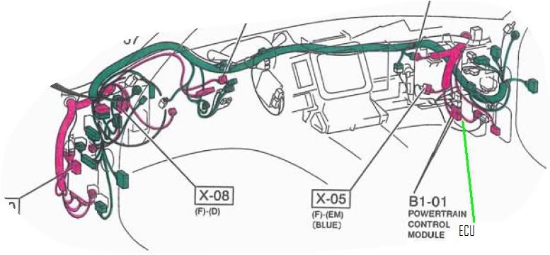
The Front harness starts at the ECU and wraps around the entire car, inputs the ignitor, then the "shielded" output travels back down the driver's side and connects to the Emissions harness (X-12), travels toward the block where another connector breaks out the IGnition harness.
No it's not Turbo'd
Joined: Jun 2002
Posts: 2,511
Likes: 2
From: Los Angeles, Ca
Doesn't the HKS (Twinpower) unit do some of the same things, since it sits closer to the coils due to plugging in-between the igniter and the coils. It interprets and conditions the quare wave, as well as amplify it.... then sends it on to the coils...
(Sory can't compete with military electronics, I have HS only)
(Sory can't compete with military electronics, I have HS only)

Rotary Enthusiast
Joined: Dec 2001
Posts: 1,252
Likes: 0
From: Sunnyvale, CA
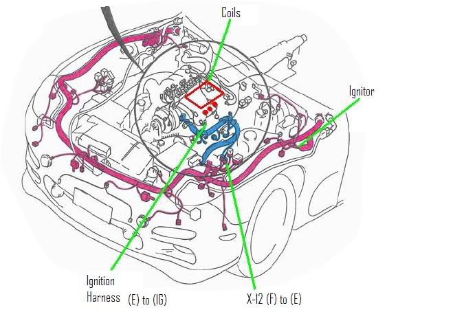
Thus, looking at your diagram.
The 8 feet the signal travels is actually from ECU to Ignitor.
From Ignitor to Coils are just about 3-4 feet then, since it goes from the pink to the blue harness color in your diagram.
As per Chuck explanation, it goes from pink to green to pink the other side, thru the front, to the blue on the ignitor/coils side.
So which one is correct?
The Front harness starts at the ECU and wraps around the entire car, inputs the ignitor, then the "shielded" output travels back down the driver's side and connects to the Emissions harness (X-12), travels toward the block where another connector breaks out the IGnition harness.
The 8 feet the signal travels is actually from ECU to Ignitor.
From Ignitor to Coils are just about 3-4 feet then, since it goes from the pink to the blue harness color in your diagram.
As per Chuck explanation, it goes from pink to green to pink the other side, thru the front, to the blue on the ignitor/coils side.
So which one is correct?
Originally Posted by dubulup
The Front harness starts at the ECU and wraps around the entire car, inputs the ignitor, then the "shielded" output travels back down the driver's side and connects to the Emissions harness (X-12), travels toward the block where another connector breaks out the IGnition harness.
development
Joined: Aug 2002
Posts: 5,714
Likes: 7
From: Lafayette, LA
Originally Posted by reza
Thus, looking at your diagram.
The 8 feet the signal travels is actually from ECU to Ignitor.
From Ignitor to Coils are just about 3-4 feet then, since it goes from the pink to the blue harness color in your diagram.
As per Chuck explanation, it goes from pink to green to pink the other side, thru the front, to the blue on the ignitor/coils side.
So which one is correct?
I didn't follow Chuck's explanation, that's why I posted the harness diagrams...also verified thru the schematics.
Originally Posted by cewrx7r1
Did you know that Mazda made another serious desgin flaw with their ignition wiring? It can be easily fixed and the result is hotter sparks even with stock ignition.
The ECU on the pasenger side, fires the ignitior on the driver side. OK we will accept this approximate 6' of wiring.
But instead of running the ignitor to coil wires directly to the coils which are about 18" away, they wired them back over to the chassis harness by the ECU, out to the harness that goes to the right front fender then over to the left front fender were it finally goes to the coills. That is about 14' of wiring.

Chuck had the right idea, but had the routing a little mixed up. Re-wiring the engine when I installed the Haltech helped edjamacate me
my ignitor outputs now run along the firewall with the engine harness, and I'm building a short harness that hits the coils direct from the ignitor (with a secret squirrel 12V switch, so I can cut ignition (coils and ignitor) with the flip of a switch in the driver's seat...a thief will never get my car started, even if he had ALL the info in the world about FD's, so shhhhhhhhhhh
none of you will be able to find the switch either )