
Why would you put a resistor across a switch?!

Thread Starter
Rotary Freak
Joined: Sep 2001
Posts: 1,500
Likes: 7
From: Lawrenceville, ga
Why would you put a resistor across a switch?!
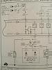
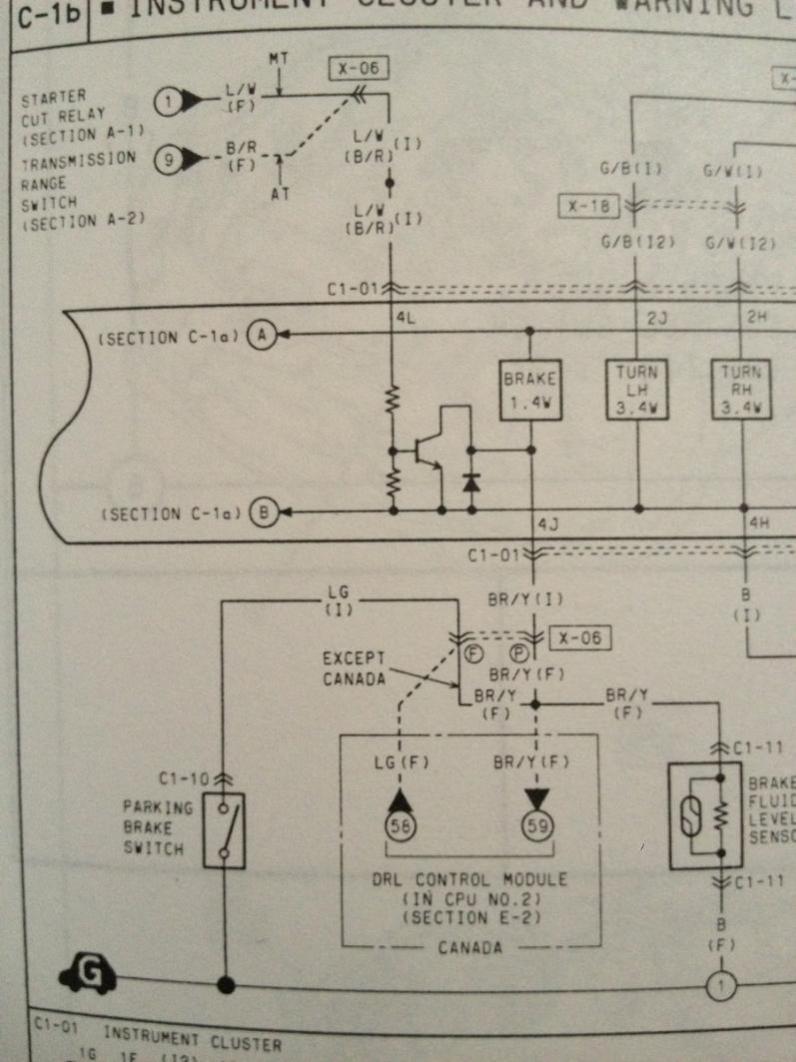
In the attached diagram of the brake warning lamp, why is there a resistor across the reed switch in the fluid level sending unit?
Also, what the HECK is that circuit next to the brake lamp or?
I need to know to resolve a crazy problem.
You can talk technically to me as I do a lot of component level repair, but I can't decode the reason for this mess.
Can you help?
Also, what the HECK is that circuit next to the brake lamp or?
I need to know to resolve a crazy problem.
You can talk technically to me as I do a lot of component level repair, but I can't decode the reason for this mess.
Can you help?


It's not that tricky of a circuit. Really, a short to ground will cause the light to come on, and that happens with the float in the master cylinder being down from low fluid level or the switch on the parking brake being closed (brake is up). You have to trace the circuit down and find out where it's grounding out.
The circuit in the brake fluid sensor is really a simple circuit, don't get too excited with how the diagram looks.
Dale
The circuit in the brake fluid sensor is really a simple circuit, don't get too excited with how the diagram looks.
Dale
It is to keep the light from coming on prematurely. It is a sensor, not a switch, so it is probably to reduce the current draw to keep the light from illuminating.
Just a guess though.
Just a guess though.
Thread Starter
Rotary Freak
Joined: Sep 2001
Posts: 1,500
Likes: 7
From: Lawrenceville, ga
Thanks to everyone so far however reply to this thread however, I'm trying to figure out why my brake warning lamp stays on all the time.
There's nothing wrong with emergency brake switch.
There's nothing wrong with the reed switch in the brake fluid reservoir.
Also, the switch in the brake fluid reservoir is a switch, not a sensor that has variable amounts of value or anything like that.
There is a magnetic reed switch passing through the middle of the brake fluid reservoir.
The reservoir float has a magnet in it.
When the float goes down to the bottom it trips the magnetic switch.
So, if the mercy brake switch is operating perfectly, and the brake fluid level switch is operating perfectly, why does my break warning lamp stay on all the time?
There is no short in the harness I've pulled it and checked.
Something is wrong with the circuit after the lamp.
Therefore I posted the question originally asking what the purpose of the circuit after the lamp is for.
Note in the diagram, there is a transistor, and two resistors attached to a diode.
I know how to read a diagram and I know how to read the flow of electricity, but I have no idea what the purpose of the circuit is for.
Does anyone here have any ideas?
I see what you are talking about now.
It would seem that by looking at the diagram then there might be a problem with the board at the rear of the cluster.
Maybe pull it out and check continuity for ground faults at the connector and also at the other locations shown on the diagram.
I do not know what the purpose of the mess to the left of the bulb is though.
I wonder if that diode possible went bad and is allowing the bulb to ground through that part of the circuit. Where does that part of the diagram lead to, I'll try to look it up now
Thread Starter
Rotary Freak
Joined: Sep 2001
Posts: 1,500
Likes: 7
From: Lawrenceville, ga
Yes I thought so too, but here's the rub..
Nothing failed or broken on the board.
Here is what I did...
I popped the pin on the brake level switch housing and removed the board.
I lifted one end of the resistor and reassembled it.
Everything works now.
Here's my guess on what is happening...
The circuit must be sensitive to current draw.
I wonder if that is true because I'm using LEDs for lights now.
I need to know what this circuit is designed to do, because I don't want to cause a problem having lifted this resistor out of the ground circuit.
I hate modding the car like this.

Thread
Thread Starter
Forum
Replies
Last Post
trickster
2nd Generation Specific (1986-1992)
25
Jul 1, 2023 04:40 PM
fastsaab
New Member RX-7 Technical
5
Aug 19, 2015 11:42 AM