When you click on links to various merchants on this site and make a purchase, this can result in this site earning a commission. Affiliate programs and affiliations include, but are not limited to, the eBay Partner Network.
So let's say you hooked your switch to the fan relay connected to the A/C control. If you flipped an in-line switch through the factory wires, nothing would happen unless the A/C were on. You are either enabling or disabling the factory control logic, that's all.
Why can't I jump the relay altogether to power the fans? Forgive my ignorance.
In my limited understanding I imagine the relay is withholding ground from the circuit, and giving ground when it so chooses.
Why can't I give the circuit ground with a toggle switch and circumvent the relay and its logic?
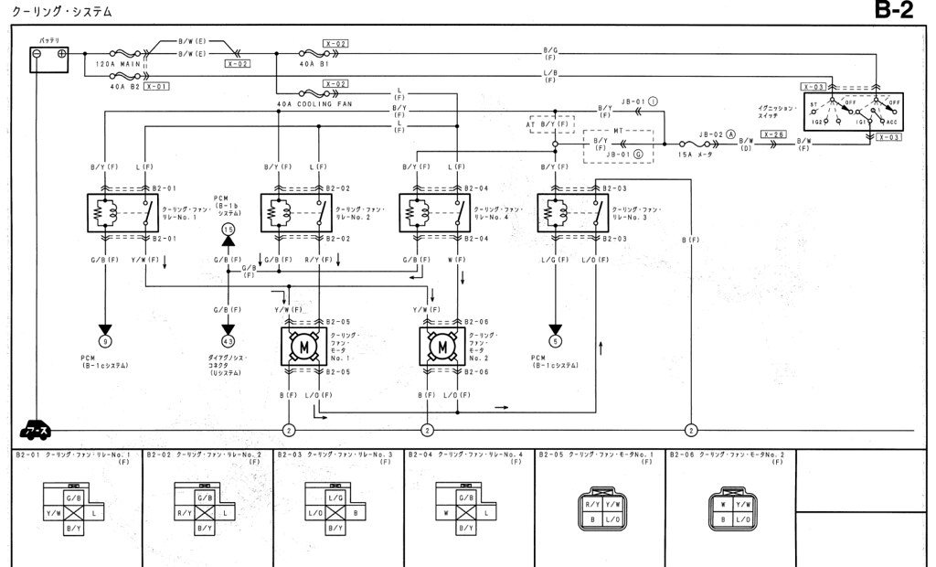
If you tied all of the ground sides of the relay coils together and ran to a switch that grounded the wiring, the fans would run on high speed not only with the switch but also on high speed with any other demand that turned them on (ECM, AC or Thermoswitch). That is a lot amperage the fans would be drawing on the charging circuit and a drag upon the enigne's performance. It may even stall the engine if at idle. Secondly, if you have the Fan Mod recall still installed and you kept the fans manually on for 60 seconds or more just before you turn the car off (ie simulating the thermoswitch being on) the recall mod will keep the fans on high when the car is turned off and no doubt challenge the battery. Lastly, if you have an automatic transmission the shift and lockup pattern will change as the trans will think the AC is on.
There is no real up side to doing this that I can see....
If you wanted to simply have a way to run the fans manually through relays 2 and 4 run a wire from the Data Link Connector terminal TFA to a grounding switch. See Arghx's schematic.
What if I grounded each relay individually with a switch? Then I could turn them on one at a time, like in stop'n'go, then shut them off when I hit highway speed.
What if I grounded each relay individually with a switch? Then I could turn them on one at a time, like in stop'n'go, then shut them off when I hit highway speed.
Re-read what I wrote in post #25 a few times. If you just hook the ground up on the factory relay(s) to a switch, you lose automatic control of the fans through the ECU, A/C, and thermoswitch. If you forget to flip the switch, you will overheat and potentially damage your engine.
If you hook a switch in-line to the factory wires, all you would be doing is disabling control with the ECU, A/C, or thermoswitch. What you are proposing would pretty much result in a fan "kill switch." I don't think that's what you were going for. You are looking to turn fans on when they normally wouldn't run, an "override" function.
A solution similar to what I proposed in post #25 would retain the automatic control of the fans but also allow you to turn them on manually. It is for a fan "override switch" using a widely-available 5 pin relay.
Personally, I would just program the ECU to run the fans when the temperatures above the thermostat opening temp. Remember there won't be much coolant flowing through the radiator when the thermostat is closed, so it's a waste of time to run the fans when the coolant is below 80 degC.
That said, it is possible to let the ECU control the fans as usual, and then override the fans and force them on using a 3-pin switch (single pole, single throw) wired as follows:
Pin 1 gets wired to the original relay control (for instance, ECU pin 3D). When the switch is in the down position, the fan will operate only when the ECU commands it to.
Pin 2 (center pin) gets wired to the fan relay. It will connect to either Pin 1 or Pin 3 depending on the switch position.
Pin 3 gets wired to ground. When the switch is in the up position, the fan will always operate.
As long as you choose a 3-pin single pole, single throw switch, it will work. The up position will join pins 2-3 and the down position will join pins 1-2. To be safe, you should use a switch that can handle at least 3 Amps. Note that if you do this with the stock ECU, it will detect that there is no longer a relay connected to its relay control pin, and it will throw a check engine code. I haven't tried this with a PFC, so I can't say how it will react.
Last edited by scotty305; Oct 13, 2011 at 11:41 PM.
Sorry to bump such an old thread but I'm running into some small problems. If I have no A/C and followed the 2nd diagram of wiring the G/B on relay 2 to V/P on relay 1, the fan is on while the car is off but the fan is off when the ignition is on. I also tried grounding V/P to a physical ground but low speed fan turns on automatically when ignition is on (I'm guessing it's the same thing as having the A/C button on?) Any ideas on using relay 1 to bump the fan speed 1 speed higher?
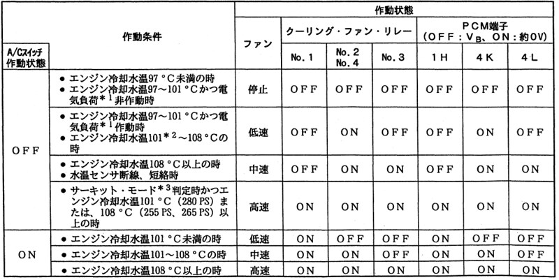
--During A/C operation the fans will be stepped 3 different speeds (low, medium, high).
--Without A/C, the fans will be stepped from low speed (PFC trigger) right to high speed (thermoswitch trigger), or from medium speed (PFC trigger) to high speed (thermoswitch trigger) depending on how you wire it.
So the new logic would be:
A/C ON, water temps below 90 C (or PFC trigger temp) -- low speed
A/C OFF, water temps below 90 C -- fans off
A/C ON, water temps at 90-96 C -- medium speed
A/C OFF, water temps at 90-96 C -- low speed
A/C ON, water temps at 97 C (FC thermoswitch temp) -- max speed
A/C OFF, water temps at 97 C (FC thermoswitch temp) -- max speed
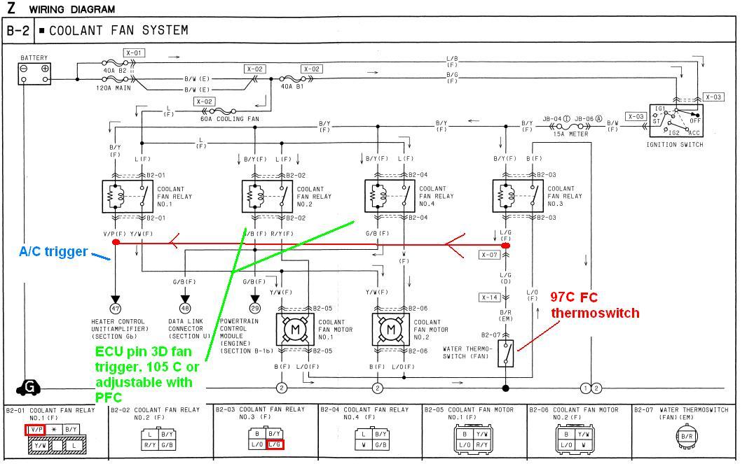
Aftercool: engine runs at 97 C for 2+ minutes before shutdown, fans run at medium speed until temps drop below 97 C, when the fans will slow down to low speed. After ten minutes the fans will shut off. No major cutting or external switches are required with this wiring. It is idiot proof if installed correctly. You could also jumper the A/C trigger wire to the trigger for the #2 and #4 relays instead of the thermoswitch. That would result in medium speeds when the PFC kicks the fan on, and high speeds when the thermoswitch comes on. It depends on your preference.
The whole point of the mod is to make it so that the A/C does not have to be on for all 4 fan relays to be engaged (max fan speeds). A lot of cars don't even have A/C anymore, or you might be driving around with the A/C off and still want to be able to get max fan speed.
I like it, just to be clear this mod will also run the fans if over 97C when shutdown and even if below 97C they will run for 10 minutes on low everytime I shutdown?
I have no AC but would like to use the button as a stepper for the fans
I like it, just to be clear this mod will also run the fans if over 97C when shutdown and even if below 97C they will run for 10 minutes on low everytime I shutdown?
I have no AC but would like to use the button as a stepper for the fans
As I understand it today, the thermoswitch input has to have been running for at least 2 minutes before shutdown for the cooling fan control module to engage the after cooling function. I don't think they will still run if you are below the 97C trigger but it might depend how you wire it.
Using the A/C switch just to bump up fans might require you to bypass some of the switches and controls for the A/C. It may not be so straightforward.
Sorry what I ment was if I switch the ac on below 97c it steps the fan up a stage (off to slow or slow to medium)
I see now, use the thermo switch as a earth trigger if switched in the last 2 minutes of driving perfect and it's only one wire across the two relays!
Sorry to hijack the thread, but has anybody access to a 95 wiring diagram, or a diagram of the harness added as part of the fuel hose re-call? I have a mysterious connector
So I purchased a 95 wiring diagram hoping for information on the re-call harness or the updated fan control wiring It was no help.
It appears as though the re-call wiring harness addition under the dash has an additional connector to ground Fan Relay #3 and activate it (in addition to the fan control module and thermoswitch)
The below drawing shows where this is (I didn't draw in the whole harness that was from the re-call) The recall harness fits in between the X-14 connector and goes to the fan control module (and this mysterious extra lead)
Any idea where this should be connected to (if at all). Could it be a test point? Conceivably, you could use this to hook up an "override" switch to activate one level of fan speed (relay #3).
Last edited by Wild Rabbit; Dec 3, 2016 at 11:57 AM.
So I purchased a 95 wiring diagram hoping for information on the re-call harness or the updated fan control wiring It was no help.
It appears as though the re-call wiring harness addition under the dash has an additional connector to ground Fan Relay #3 and activate it (in addition to the fan control module and thermoswitch)
The below drawing shows where this is (I didn't draw in the whole harness that was from the re-call) The recall harness fits in between the X-14 connector and goes to the fan control module (and this mysterious extra lead)
Any idea where this should be connected to (if at all). Could it be a test point? Conceivably, you could use this to hook up an "override" switch to activate one level of fan speed (relay #3).
Did you work out how to do this?
i now have the Fan control module (N3A7 18 701) and want to get the fans to run 10 minutes after switch off but like you say there is no or little info on the wiring harness that was added to do this


 . In case anyone else needs the info, here it is: