
"Why is this engine so damn complicated??" Part 1: Sequential turbos demystified


It looks like an acceptable boost curve to me, although I still think a higher flowing wastegate would make the creep less likely to occur. I'd be curious to see what happens to the boost curve if as a test you change your IGL map to effectively disable the safety row. I don't think it would be particularly risky.
I agree, it is acceptable, but this is because I adjusted the duties (the sec in particular) down to 65% and I am happy to run at "only" 13 psi. And you are right, there won't be much change even if I disable the safety row because it is "almost there". The thesis I am trying to prove though, is that if for instance i want to run at 14 or 15 psi (rather then my current 12.5-13), then I will have to increase the sec duty value - say to 75% or more. But by doing so, I found out that the PFC will have hard time controlling boost creep under my conditions (as you can see, everything happens in only a few seconds) because the WG% duty will not drop quick enough and open the WG decisively enough to divert more energy from entering the turbine. Porting the WG would certainly help because it would compensate for the relative slow control system, but not because the stock WG is small (that is proved by my other test run with minimum duty set, like 25% - no boost creeping there, but also no much boost either). It is just that the control system does not open the WG quickly enough. Besides, WG porting for me is not an option. Not allowed allowed in my autox class; I am only allowed to play with the control system (whether PFC, EBC or check/control valves)
Having said that, I am good and satisfied with this compromise for the time being, and happy to run at "only" 13 psi, and I can make the PFC work for that in 1st and 2nd gear. Incidentally, the main reason I am running 13 psi and don't want more than 14 psi is that I still have the stock injectors and want to keep some margin available, hence the safety row at 19600 and my unorthodox control strategy of pulling the IGL to zero at and above that.
Thanks for your comments and suggestions.
- Sandro
It's kind of hard now to provide precise answers because I am quite behind in analyzing my data systematically. Have a lot of logs but couldn't find the time to sort them out systematically. However, as a general trends I found out that the the sec target boost counts close to nothing at least initially; maybe because my transients are so quick and the logic may be more a PI with small P and more I. Definitely, with the sec it is the duty value that counts the most; and the logic appear to react pretty fast to changes in boost, more than the absolute boost value. On the primary though, also the target boost seems to have quite an influence, not just the duty. I am attaching three pulls where - in the primary - I only varied the target boost not the duty.
80.56 70.64 peak PIM before transition ~ 17400
90.56 80.64 ~ 18000
95.56 85.64 ~ 18300
With 100.67 I am now making 19500
80.56 70.64 peak PIM before transition ~ 17400
90.56 80.64 ~ 18000
95.56 85.64 ~ 18300
With 100.67 I am now making 19500
They refer to boost targets and duties, primary and secondary
Eg. 80.56 70.64 identifies the log with these settings:
Primary 0.80 Kg/cm2 and 56% duty
Secondary 0.70 Kg/cm2 and 64% duty
17400, 18000, and 18300 are the approx peak PIM values before transition reached in the three runs.
Since the duty in the Primary is kept constant at 56% in all three runs, the logs show that higher Primary boost targets cause higher boost before transition.
On the secondary, the the 64% is also kept constant but the incremental changes to the secondary boost targets (similar to the increments in the primary) do not cause appreciable boost changes.
On the secondary, the the 64% is also kept constant but the incremental changes to the secondary boost targets (similar to the increments in the primary) do not cause appreciable boost changes.
I was thinking on how to "improve" the PFC boost control with a minimum of complexity.
The PFC limit I see and would like to overcome is as follows. Based on my logs, it appears that when I set high duties, I cannot stop boost creep due to the inability of the PFC of adjusting down the duty quickly enough. As a result, the WG gets only partially open.
Conversely, if I set the duties low, the WG opens wide enough to stop boost creep but then, I would not be getting much boost in general.
About installing a fast solenoid controlled on-off valve on the WG bleed line, controlled by the pressure in the intake manifold?
You could then set duties high enough to quickly reach your desired boost level, as the PFC is very capable of doing. But when the manifold pressure reads high, then the on-off valve would close, stop the bleeding from the WG actuator, and [in theory] cause the WG to open fully. Clearly, to be seen if this could be implemented with sufficient dynamic performance.
Are you talking about switching to a 3-way solenoid as found in typical external aftermarket EBC's? That seems like the simplest thing to try.
http://www.frightprops.com/FrightPro...ID=A-0013-0082
dudemaan recommended these to me. This is actually the same solenoid as used for the AEM EMS, except without the price markup. buy two of the 1/8 NPT ones. it's a lot cheaper than buying the Apex'i ones. I didn't get one because you don't really need 3 way solenoids for an external wastegate.
In your case you would just cap off the line that normally goes to the factory wastegate/precontrol solenoids. Then wire the new solenoids into the harness, either hardwired or by finding the OEM style plug. The instructions should say which ports are normally open. This would set the wastegates up for "blocker" style boost control, where the pressure signal is cut off from the wastegate. These types of systems require far less duty cycles than bleed types, and are more responsive. It is very common to switch from a bleed type controller to a 'blocker' type controller on Subarus, while retaining the stock ECU as a boost controller and changing the duty values.
If this works, you should do a writeup on it.
Thanks. Actually, what I had in mind was to retain the system as it is - with the stock bleed solenoid valves controlled by the PFC.
But to add a simple two-way / two-ports solenoid valve, driven by a separate (from the PFC) pressure signal (e.g. a pressure switch or a relay). Not expecting it to be "cycled". Just to be closed on high pressure, while otherwise normally open. The valve to be installed on the bleed line between the WG actuator outlet and the stock (cycling) solenoid valve.
The idea is to have it normally open - leaving it to the PFC to cycle the stock solenoid - business as usual. But, if the pressure reaches a high setpoint, an independent signal would close this new valve and stop the bleeding from the WG actuator. That should cause the actuator to move and fully open the WG. Probably, only one valve at the WG would be sufficient. I don't seem to have any problem before transition.
One more question. Do you know of any source for a sturdy 0-5 V pressure sender to read and log pressure values in the PC and WG actuators? That would be very valuable information to have, I guess.
Unfortunately, the PFC doesn't have very controllable switched outputs. The only real switched outputs are the charge control and turbo control outputs, and those are switched by rpm (Turbo transition settings table) not boost.
You would need a separate controller. To do it right you would need an initial trigger pressure, hysteresis control (how much the boost has to drop before the solenoid disengages), and some kind of time delay to account for solenoid lag (just like injector lag settings). Otherwise you could have a very unstable system where this auxiliary solenoid engages, boost drops, then the PFC cranks up the duty and boost overshoots then drops again as the auxiliary solenoid comes back on. It seems like unneeded complexity and a lot of trouble.
Again I encourage you to try a 3 way solenoid on the wastegate side.
You are probably right. I will be looking more into the 3-ports valve. I found this good technical piece http://www.perrinperformance.com/pages/show/113
Interesting concept. Blocking the feed and opening the bleed at the same time. Kind of "doubling" the gain. Thanks.
Interesting concept. Blocking the feed and opening the bleed at the same time. Kind of "doubling" the gain. Thanks.
See also https://www.rx7club.com/showthread.p...87#post9572487
Thanks.
- Sandro
Subaru OEM boost control systems are among the most sophisticated ones out there. In addition to solenoid duty tables, boost target tables, and PID gain tables, they have correction tables for air temp, coolant temp, and rpm. They also disable the solenoid if a certain knock threshold is reached. You can see in that article how Subaru owners take their factory control logic framework and use it with different types of plumbing configurations for different applications.
Just as Subaru owners can install a 3 port solenoid to control an internal wastegate instead of a 2 port, I installed a 2 port solenoid on a PFC (used a factory one actually) to control an external wastegate. If you understand how all the plumbing works you'll realize why so many variations can be done with the same style control logic.
Note that the Apex'i AVC-R solenoid will connect directly to the stock harness with no wiring modification required. It is the same solenoid that is supplied in the PFC boost control kit, along with a 3 bar Denso MAP sensor.
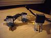
Pic of the MAC and the Apexi 3-way solenoid valves side by side.
Note how relatively small the MAC are.
The MAC shipped with no fittings (and no electrical connectors).
Ports are threaded 1/8" NPT
I screwed in barbed fittings
Note the "mufflers" screwed in the vent port, one is a sinterized plug, the other is a needle valve
Note how relatively small the MAC are.
The MAC shipped with no fittings (and no electrical connectors).
Ports are threaded 1/8" NPT
I screwed in barbed fittings
Note the "mufflers" screwed in the vent port, one is a sinterized plug, the other is a needle valve
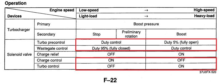
I'll put up Sandro's log to illustrate a few things. He goes through transition one time and then stays non sequential for the rest of the run. First, take a look at this description of how the solenoids should operate from the factory:
Now here's an excerpt from Sandro's log. Sorry there's so much crap on the screen, I'm trying to get a lot of points across with one screenshot. I am assuming he is using default turbo transition settings.

symbols:
TCN ---> Turbo Control solenoid. A value of "1" means it is energized, "0" means it is not.
CCN ---> Charge control solenoid. A value of "1" means it is energized, "0" means it is not.
PIM ---> Manifold pressure value. 10000 is atmospheric pressure, 20000 is 1.0 kg/cm^2 boost, and any values in between
PC% ---> Precontrol solenoid duty. More duty = actuator more closed (higher boost)
WG% ---> Wastegate solenoid duty. More duty = actuator more closed (higher boost)
TPS V ---> Throttle position sensor voltage. Technically 100% throttle is somewhere between 4.2 and 4.6 volts
Now here's an excerpt from Sandro's log. Sorry there's so much crap on the screen, I'm trying to get a lot of points across with one screenshot. I am assuming he is using default turbo transition settings.
symbols:
TCN ---> Turbo Control solenoid. A value of "1" means it is energized, "0" means it is not.
CCN ---> Charge control solenoid. A value of "1" means it is energized, "0" means it is not.
PIM ---> Manifold pressure value. 10000 is atmospheric pressure, 20000 is 1.0 kg/cm^2 boost, and any values in between
PC% ---> Precontrol solenoid duty. More duty = actuator more closed (higher boost)
WG% ---> Wastegate solenoid duty. More duty = actuator more closed (higher boost)
TPS V ---> Throttle position sensor voltage. Technically 100% throttle is somewhere between 4.2 and 4.6 volts
Why do you think Mazda chose to set the sequential system to kick back in at 3000 RPM? Why not 4000? Would that not make it seem more responsive in stead of waiting for the car to go back up the RPM band?
Is there some reason why not to do adjust the trigger point?
Why do you think Mazda chose to set the sequential system to kick back in at 3000 RPM?
...Why not 4000? Would that not make it seem more responsive in stead of waiting for the car to go back up the RPM band?...Is there some reason why not to do adjust the trigger point?
Adjust it by feel. It's not going to hurt anything. Although I did once set all the "high" trigger points extremely low (1500 rpm or something) and all it did was confuse the PFC. The charge control valve appeared to be held closed, and the charge relief was basically venting all the boost back to the air cleaner so the car only made 1psi peak. Putting the settings back immediately fixed it.
My car was bone stock with the sequential system intact when I got it, and I drove it around that way for a while (installed a downpipe and boost gauge and ran that way for a couple years, but I don't think that changed the feel very much). The only time the stock ECU's sequential control felt odd was if going around a sweeping turn in 2nd gear at the autocrosses, the sudden surge in power when the second turbo was added became noticeable and it sometimes made the car want to spin. Then again my previous autocrossing experience was in a non-turbo 165hp AWD Subaru so I was definitely in the habit of mashing the throttle early in the corner and letting the all-wheel-drive pull the car forward rather than causing a spin.
Aside from that, I don't think I ever noticed the mid-RPM lag you're talking about, Double-J. I suspect I probably encountered it (put about 20-30,000 miles on the car with the stock ECU) but didn't notice it.
Now with an aftermarket ECU, I've moved the sequential transition lower (occurs near 4000RPM now), I think the car feels more predictable during transition.
I know the exact "lag" he's talking about. Start out from a light, shift at 5000 rpm. 1st feels responsive and secondary turbo comes online. RPMs may drop to what, about 3200-500? again it depends on the flywheel and how you drive. But the engine stays in non sequential mode, so 2nd feels sluggish as you ease into it. It builds boost a lot slower than 1st did, because 1st was initially spinning one turbo while 2nd gear is now spinning two just as you open the throttle. So I raised the sequential transition hysteresis "Turbo transition low" to 3500 rpm. Once the car goes into 2nd, it's usually spooling one turbo and feels more responsive. It only seemed to make a difference during that kind of situation. I've never tested this in an autocross type of scenario.
That's right arghx.
If you drove the car aggressively you wouldn't notice it because you are staying above the transition point.
But like how you described if you fall below because you shifted at 5000RPM then you have some lag till the RPM's build up again.
By raising it 500 RPM that would help out but why not 4450 so it will practically be sequential all the time?
The "low" value needs to be less than the "high" value. If you raise the "high" value (main transition point) too much, power will start to fall off as the primary turbo runs out of breath. It's like setting VTEC too high on a Honda. If the "high" and "low" values are really close together you might have the engine rapidly going in and out of transition all the time which would slow the car down. You just have to experiment with it.

Luckily no broken cambelt
Joined: Nov 2009
Posts: 97
Likes: 0
From: Sweden
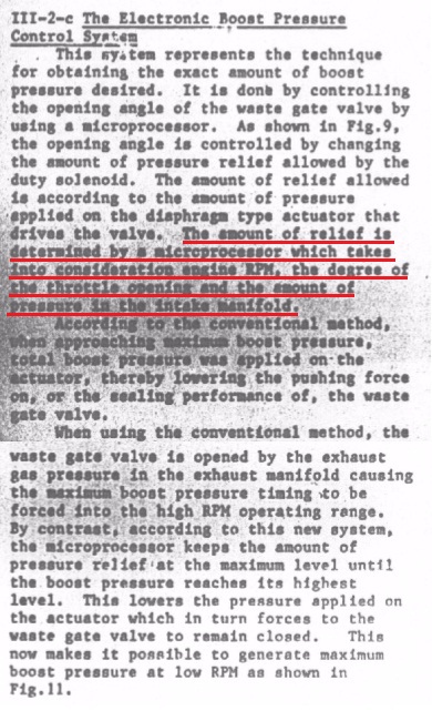
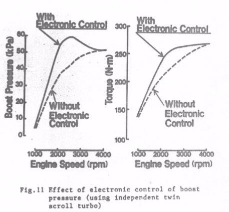
I recently found this great thread. Really interesting about the boost pressure feedback control system, as it on Robinette's page is stated to be an open loop control system.
A question about your attachments. Some look like they come from the workshop manual. The second attachment in the first post, the first in the second post and the one about the boost control system, but I can't find these in my 94 manual. Where did you get them?
Some remarks...
If the two compressors were connected to each other while only the primary makes boost the secondary would be put into surge (backwards airflow), which can lead to compressor destruction. (Perhaps "can" should be replace by "most likely" considering that no surge valve (BOV) during a tip out maneuver can be enough for destruction). Therefore it is not really an option to let the air go into the engine until both compressors are making equal amounts of boost. The charge control valve is clearly needed.
Some on PID-controllers: A P-controller (pure gain) will always have a stationary error as it gives zero control signal when the error is zero and zero control signal is not sufficient to give zero error.
To avoid this steady-state error the I-part is needed.
In your figure that describes the P,I and D part of the controller the I and D part seems to be switched. When the boost is steady the D-part is zero and does not have any effect. The D-part is proportional against the rate of the error.
A question about your attachments. Some look like they come from the workshop manual. The second attachment in the first post, the first in the second post and the one about the boost control system, but I can't find these in my 94 manual. Where did you get them?
Some remarks...
As the secondary turbo starts spinning up (but before it is ready to come online), the air it compresses can either go into the engine or not go into the engine (duh). Mazda chose to keep it out of the engine, perhaps because it minimized the amount of calculations that their 8-bit (8-bit like an NES with Duck Hunt and everything) ECU would have to perform.
Some on PID-controllers: A P-controller (pure gain) will always have a stationary error as it gives zero control signal when the error is zero and zero control signal is not sufficient to give zero error.
To avoid this steady-state error the I-part is needed.
In your figure that describes the P,I and D part of the controller the I and D part seems to be switched. When the boost is steady the D-part is zero and does not have any effect. The D-part is proportional against the rate of the error.
I recently found this great thread. Really interesting about the boost pressure feedback control system, as it on Robinette's page is stated to be an open loop control system.
A question about your attachments. Some look like they come from the workshop manual. The second attachment in the first post, the first in the second post and the one about the boost control system, but I can't find these in my 94 manual. Where did you get them?
A question about your attachments. Some look like they come from the workshop manual. The second attachment in the first post, the first in the second post and the one about the boost control system, but I can't find these in my 94 manual. Where did you get them?
If the two compressors were connected to each other while only the primary makes boost the secondary would be put into surge (backwards airflow), which can lead to compressor destruction.
Some on PID-controllers: A P-controller (pure gain) will always have a stationary error as it gives zero control signal when the error is zero and zero control signal is not sufficient to give zero error.
To avoid this steady-state error the I-part is needed.
In your figure that describes the P,I and D part of the controller the I and D part seems to be switched. When the boost is steady the D-part is zero and does not have any effect. The D-part is proportional against the rate of the error.
To avoid this steady-state error the I-part is needed.
In your figure that describes the P,I and D part of the controller the I and D part seems to be switched. When the boost is steady the D-part is zero and does not have any effect. The D-part is proportional against the rate of the error.
Luckily no broken cambelt
Joined: Nov 2009
Posts: 97
Likes: 0
From: Sweden
They say they take the boost pressure into consideration so it is some sorts of closed loop control.
One common way to design a controller is through "try simplest thing first" = "try p-controller first". The oems probably found the p-controllers sufficient, except for Subarue who didn't like the inherent steady-state error and therefore added an integral part. Of course ecu performnace could be a factor too.
One more explanation of the PID controller that might help the intrested:
The P-part looks at the current error, the I-part on the past errors and the D-part on the future errors. By noticing if an error has been present for a long time the I-part can eliminate steady-state errors. By looking at the rate of the error the D-part can for see how the error will look in near future.
Now I have to read up on the service highlight documents...