When you click on links to various merchants on this site and make a purchase, this can result in this site earning a commission. Affiliate programs and affiliations include, but are not limited to, the eBay Partner Network.
Is that harness connected correctly, or not. Best not guess.
Black/Red wire is Power for all 3 coils. At the Coil connectors the fire colors are as follows: Trailing #1 (Front) is Red, Trailing #2 (Rear) is Blue/White, Leading is Yellow/Blue.
Anyway, stuff just got real now
Couldn't pass it up for $40, and a couple extra 19" screens from a previous setup. Perfect way to stay useful and busy with it going full crap weather this weekend.
Seems it was worthy of some discussion (2009 Dec. 9th issue of HYPER REV).
HyperRev Magazine, vol.144
Seems the article does not give a reason for change other than "model change". It does say you should change the plug wires annually and the short harness every 70,000 km.
Coincided with the introduction of the "rat box'. Possibly electrical interference between the coils?
Explanation in manual says:
"Ignition Coils:
Position of coils has been changed.
Coils, themselves, have not been changed."
(To be verified by Akagi.)
Text checks out, it's good. As for why they shuffled them around, my best guess is to make a little more room for the solenoid box's connections in the middle.
I already have it in VERY high resolution, it's part of this project Started putting the new English text back in a couple days ago while getting the items that need verified together in a cohesive order, checked against the parts catalogs. Kinda like magic :P
Just a quick update. I just finished text on Section E a few minutes ago. Gotta say that keeping my focus at 100% while split between 4 screens is harder than I thought. That and I noticed my keyboard has been skipping or mixing up keystrokes every so often. Add in system lag that creeps up with 15+ windows open and it does dampen progress a bit. But on the plus side, the next-to-final text is about 1/3 done now (126/408). With that in mind, here's a quick breakdown of everything remaining to be done on the entire project.
Connector header text (in progress)
Add connector images
Text Bubbles for diagrams and locator pages
Render pages in PDF, then final assembly.
So the goal is in sight, and I'm trying my best to get it finished by the end of the year.
Interesting note Redbul, I never knew about the second leading spark per rotor.
I just finished all of the connectors, that was a LONG slog. I wasn't too happy with Section X: Common Connectors and how it was going to end up being a mess, complete chaos, or nowhere humanly readable to make straightforward comparisons. So it got re-sorted, plus an overhaul and a massive upgrade.
Section X is always kind of an odd one since it's only connectors. Still not "perfect", but good enough to work with until pictures are put in and things can be tweaked where needed. Color coding makes it a TON easier to follow if things get goofy. Also, re-sorting them fixed a few discrepancies too. Win Win.
Gomen ne for the lack of updates since November. I've been occupied by a rather dreadful project called "fix the daily's coolant leak". It's a story in and of itself, full of swearing in German, missing documentation and geometric challenge. But I'll explain it meme for brevity here:
There's over 100 pictures of it that were necessary to handle it in the proper Japanese manner that is my trademark on any procedure.
Anyway, work has now gotten back on track and connector images are being imported into each page right now. Everything needs the image sizes unified, but I can do that once the daily is taken care of this week. Either way, progress is moving forward again.
Took a day or two to re-learn how to organize all of the open windows. And then I realized I um...forgot to draw up the final size specs. Or I misplaced them from months ago, I can't remember which. So once Section B has the images fully imported, I can fiddle around with filling the holes with different sizes to see what works best. Pretty sure that's what she said too
So I'm about 3/4 done ironing out the discrepancies in connector images and got thrown a massive curve ball while checking/confirming the A/C Pressure Switch. Standard procedure is to verify it with an original on the actual car, but I definitely wasn't expecting this. G1-xx is for the normal A/C system, akin to what came in the North American models. G2-xx is the Auto A/C system.
Here's all of them in a single image. I didn't have the USDM 1995 Wiring Diagram, but I'm sure it's identical to the USDM 1994 one. Opened up a massive wormhole trying to find the part in question to get an actual image of it. But that led to a big problem. There isn't a part number for the Pressure Switch. It comes as part of one of the Refrigerant Pipes on all Denso systems. MANA systems have it as an individual part, but that's a story for another day.
This is Front Harness side of the connection, so the image of the actual connector is correct.
Out of 13 different diagrams (includes USDM 1995), only the absolute last one was right and it took almost a decade for anyone to notice.
I've been hard at work, hammering out the last bits before the final phases can begin. Just like with the A/C Pressure Switch, there were a few other connector discrepancies that had to be resolved, some of which followed the trend of "last second fixes" from the A/C Pressure Switch.
I had a change of heart on Section X and ended up redesigning it from one column per sub-model to a row for each sub-model. It just worked better when disproportionately wide or large connectors were factored in. Making any necessary adjustments is much easier and one can easily follow changes throughout the years by going down the appropriate column.
And I've been busy getting the final sizing/fitting underway. Section A went together with no fuss. Section B needed some customizing, but fits together even better than I imagined. All of the description text is 12pt, so there's more than enough space for text in each terminal's cell. The ECU connectors are just placeholders for the moment. I re-drew them awhile back and they're getting the last few adjustments now.
Merry Christmas, I hope everyone had a nice one. I've been busy putting all of the connector images back in their proper locations. I didn't keep count, but there's a LOT of them and it took a few 8+ hour days to get through the whole bunch.
Right now, I'm doing a quick run-through to see what sections are good to go for text and what needs adjustment to some degree to fit properly on the page again. So far, it's about a 50/50 split between the two, so it'll save me quite a bit of work later. While adding connector images, Section X: Common Connectors received a big upgrade for readability and quick, easy comparison between versions. No spoilers, you'll see when it's done. But I will say that the Modular Block Format has earned its keep.
Everything is looking like the Final Text will be starting around the 1st.
Good to hear the your labours will soon bear fruit.
Thanks Redbul. I JUST finished fitting all of the connector images in their cells. One particularly troublesome pair of connectors resulted in their parent page being redone not one, not twice, but SIX times before I was happy with it.
So I'm gonna say it. We are now in the Endgame. The last leg of the race. The final chapter. One day to rest, resupply, recharge and re-center. Then cue up the final stage music. Everything is set, ready, prepared and primed to go.
So I took a very needed break to get myself back up to 100%, and got back to work today. First up is hammering out the overall "rules" for all of the text being put in and figuring out how everything should look, fit, etc using the Version 1 Starter page as a guinea pig.
All of the odd bits have unique identifiers so they can easily be zeroed in on. redirects are Rxxx and in Red on either light blue or yellow background, Terminal Number/Letters are #xx and in Blue on an orange background. Grounds are Gxx, in Black on a green background. Easy to spot or use the handy search function to target them.
This put the spotlight on a couple minor things to be optimized for efficiency. In short, almost all the text can be pre-formatted en masse to save a ton of time. Spend a day, save a month. It's a good trade.
Every text item has an alternate specification if necessary on some of the densely-packed parts like Engine Control. Probably won't be needed, but always good to be prepared.
Super Ninja Edit: Just finished the first page
Thoughts, feedback, ideas? I'm all ears
Last edited by Akagis_white_comet; Jan 2, 2024 at 01:24 PM.
Reason: First prototype page
So I went through all of the text over the past few days to pre-format everything. Uncovered a few minor errors that got fixed on the spot and discovered that I um...forgot to unify all of the Wire Color Modifier Conditions.
So there was some swearing. And while going through everything, I discovered a few pages that might be troublesome to put in the newly-unified Modifier Index in its pre-designated spot. Didn't disappoint either, Sections B and S were the bugger sections.
Some reorganizing later and said Modifiers are in place in one of the 11/91 ECU pages as a test run. But it did mean moving connectors around to make space in an already cramped area. Not fun, but it still looks good. The only downside is that the ECU Pinouts had to be reduced to 10pt instead of 12 like everything else. Like it or not, terminals with Light Green/Any Color wire, plus a Modifier (Auto A/C, Sunroof, etc) just wouldn't meet my standards for legibility and fit/finish.
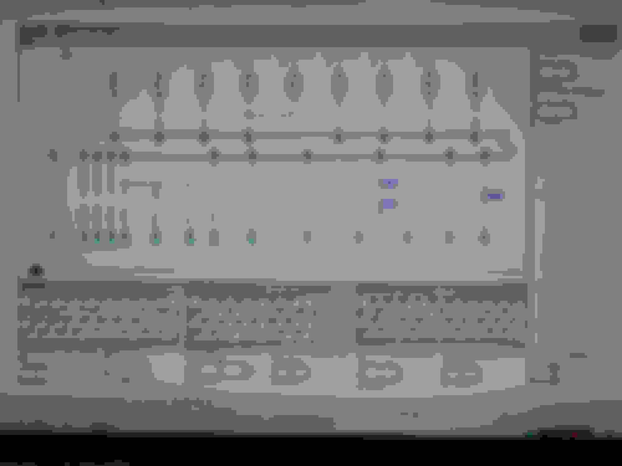
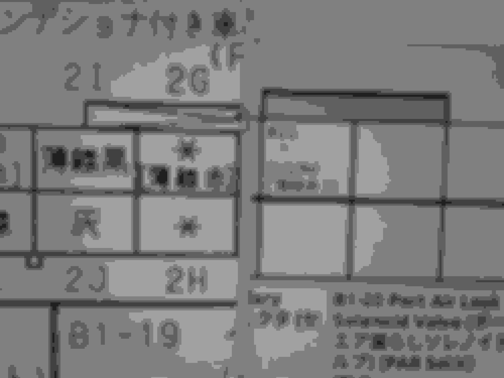
Here's the test page, I think most of the bugs are ironed out now. ECU connector area has to be split then recombined on a per-pin spacing, so it's as close as humanly possible.
Comparison on ECU Pin 2G between original Japanese and English+Japanese. The B1-20 Connector Description Text is 12pt Bold for comparison.
As long as I don't encounter a terminal with Light Green/whatever, plus a Modifier that ALSO uses Light Green/whatever, we SHOULD be okay now. The rest of Section B will be getting the required modifications soon. Still have to come up with a solution for Section S (11/91 through 12/95), but it shouldn't be as difficult now that I have an idea of how to do it.
After taking notes on everything while putting in the Modifier Text in each section, I took a bit of a detour to tidy up the chaos better known as Section JB: Joint Box and W: Power Distribution. Anyone that's seen the diagrams from a North American FD knows how they're hard to follow.
These sections for Japanese FDs are worse, and I couldn't just leave it in monochrome spaghetti chaos. Now they're fixed so a human being can follow them. No pictures this time, you'll just have to wait and see.
While fixing the Joint Box internal diagrams, I made another discovery. They're all wired the same because they're all identical. F100-66-730A is used on every single Japanese FD. The harnesses and TWS Unit are just tailored to the specific options (Sunroof, Rear wiper, etc) available for the specific sub-generation. I had a feeling about this for awhile now, but now it's confirmed.
After de-spaghettifying the Joint Box and Power Diagrams, another pass was made through every section to tidy up any loose ends, fix formatting, etc. I JUST finished it about an hour ago, time very well spent too. Ended up breaking a couple of my old formatting rules in spots, and having to redesign it completely in a couple areas, but it is still clean, tidy and well-organized. No teasers this time either, you'll just have to wait and see when it's done. Trust me, you'll love it.
Backups are made, everything's packaged up now, and ready for final assembly, take 2. So, copy-paste marathon with pre-formatted text on 400+ pages. And I need a day off. So I'm taking one now
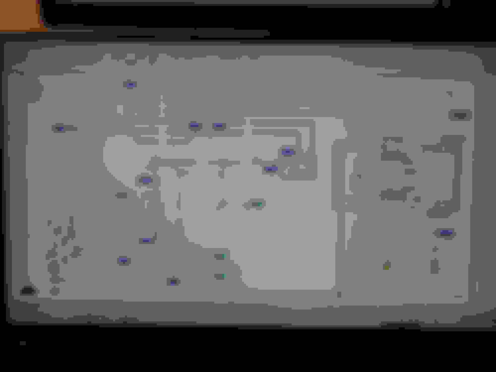
I've been busting my butt to get this done, but Section W is there now. The first six diagram pages are done. Including all of the chats/etc, Finished page count is now at 88 of 500
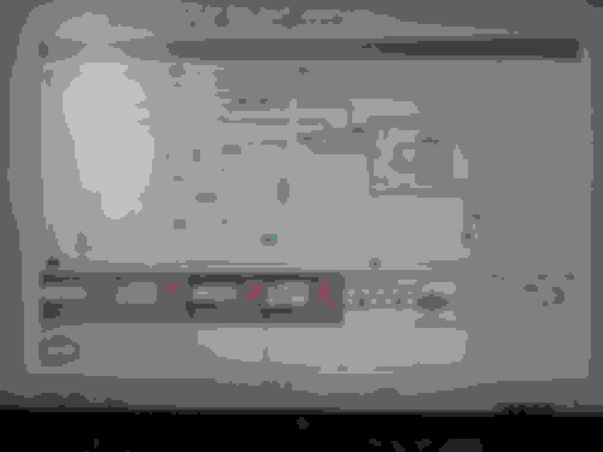
Couldn't resist taking a screenshot for this monumental occasion.
I've been chugging further through the Joint Box today and got the first external diagram finished a few minutes ago. Putting in the Terminals and Wire Colors manually is slow and tedious work despite everything being set up in a chart months ago. But thanks to the foresight of using the best example of each image, the remaining Joint Box diagrams can be copied/pasted in batches for a BIG speed gain.
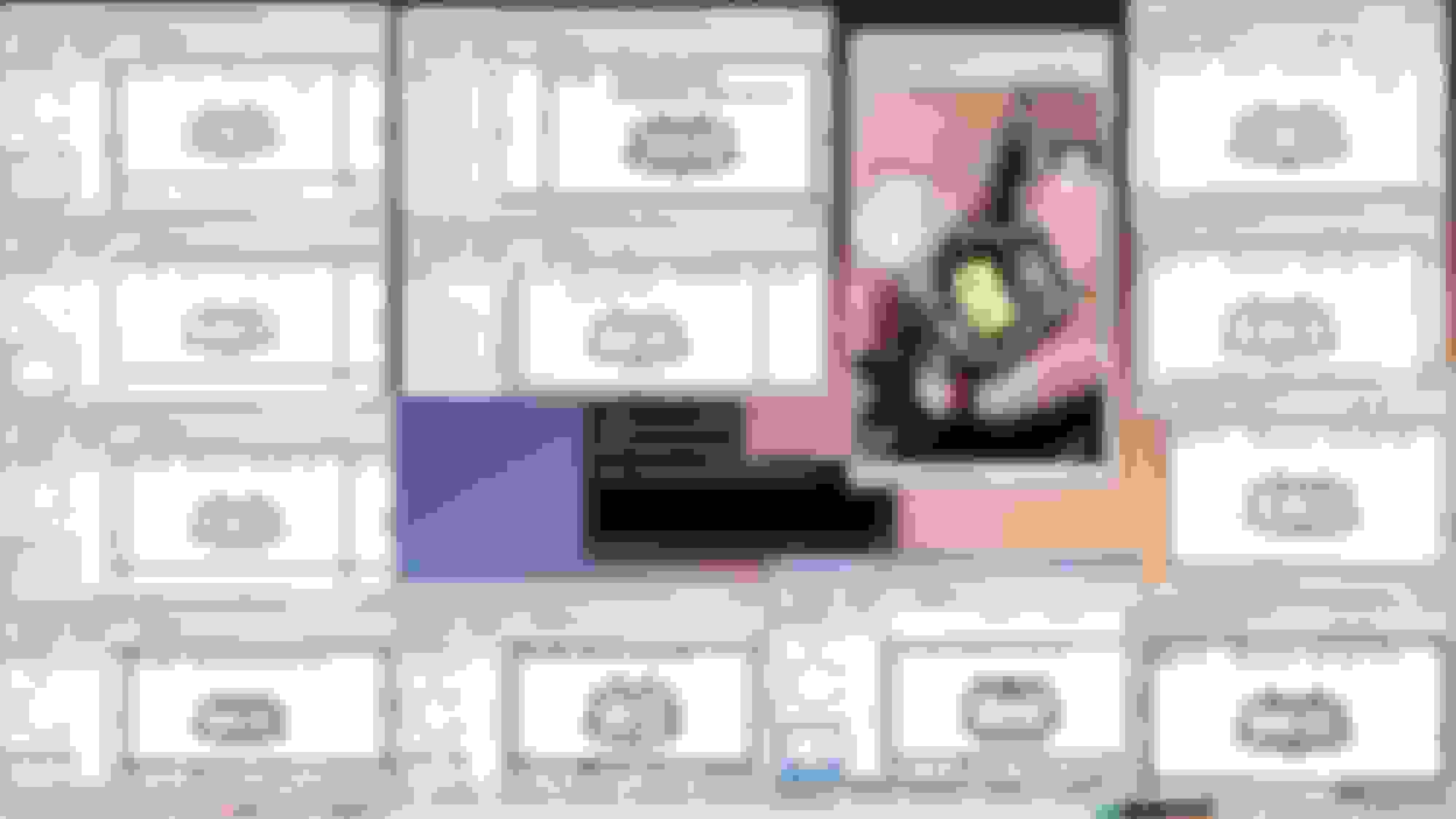
Anyway, I ended up redoing the Joint Box external diagram since I wasn't happy with it. First 3 on the left are what WAS going to be used. The one on the right is the final version.
And it means I don't have to adjust each connector pinout's details every time. Spend a couple hours, save 3 days? Win Win. Gonna finish the rest tomorrow.
My thoughts exactly. It's at least a weekly thing now that someone contacts me either about a Cosmo or a Japanese FD anymore. So I guess I'm doing something right
The 100th page of this whole project just got finished a few minutes ago. There's 400ish to go, but Section W: Power System and JB: Joint Box are finished and rendered in PDF now. Gave the Joint box another minor readability upgrade on the schematic page for quick, easy comparison between versions (hint: option retrofitting). I've found a decent rhythm for the process now, the first page takes a bit since it has to be done piece by piece. Then it can be batch-copied to the remaining applicable pages for that section and adjusted accordingly for placement, colors, etc
The Joint Box external page for Version 1 took a whole day to put everything in (9 connectors, lots of wire colors to fill in). The remaining 5 took about 4 hours, including proofreading and making all of the adjustments for different options.


 Started putting the new English text back in a couple days ago while getting the items that need verified together in a cohesive order, checked against the parts catalogs. Kinda like magic :P