When you click on links to various merchants on this site and make a purchase, this can result in this site earning a commission. Affiliate programs and affiliations include, but are not limited to, the eBay Partner Network.
This is the type of setup I always run when I install them for many of the reasons others have stated. One thing you need to watch out for is catch can placement especially in high humidity environments. You want to place the can near the turbos if possible to keep the temperature in the can up. If you don't, the can will fill up with water due to the water vapor condensing if its in a cool enough location for water to become liquid again. I have this same Greddy catch can on the wife's car, has been on there for 20 years but the bay is so tight that I can't fit this particular can in a warm enough location to keep the humidity in vapor form. I plan to build a custom setup when I update the car. Because of this and me living in Florida now, during an AutoX day I have to dump the can twice, once after the morning session and once after the later session and it just fills with water not oil. It wasn't as bad when I lived in Dry Colorado but still noticeable. I catch very little oil in the can but have to regularly dump it for water even for street driving. When I am able to install these in the hotter parts of the engine bay, I don't have this problem.
I didn't consider the high humidity; I'm also in Florida. Luckily, I'm not tracking the car yet. However, I think there's a second solution you can opt for. They make built-in heaters that utilize your coolant as heat (like our throttle bodies do from the factory, which helps melt ice off the butterfly valves in cold climates). If mounting it closer to the turbos is not an option, then I'd say you could T off the same hoses to the throttle bodies to feed into the inlet and outlet of the heater core for the AOS. You might have to modify one to keep it as a catch can since AOS routes oil back into your engine.
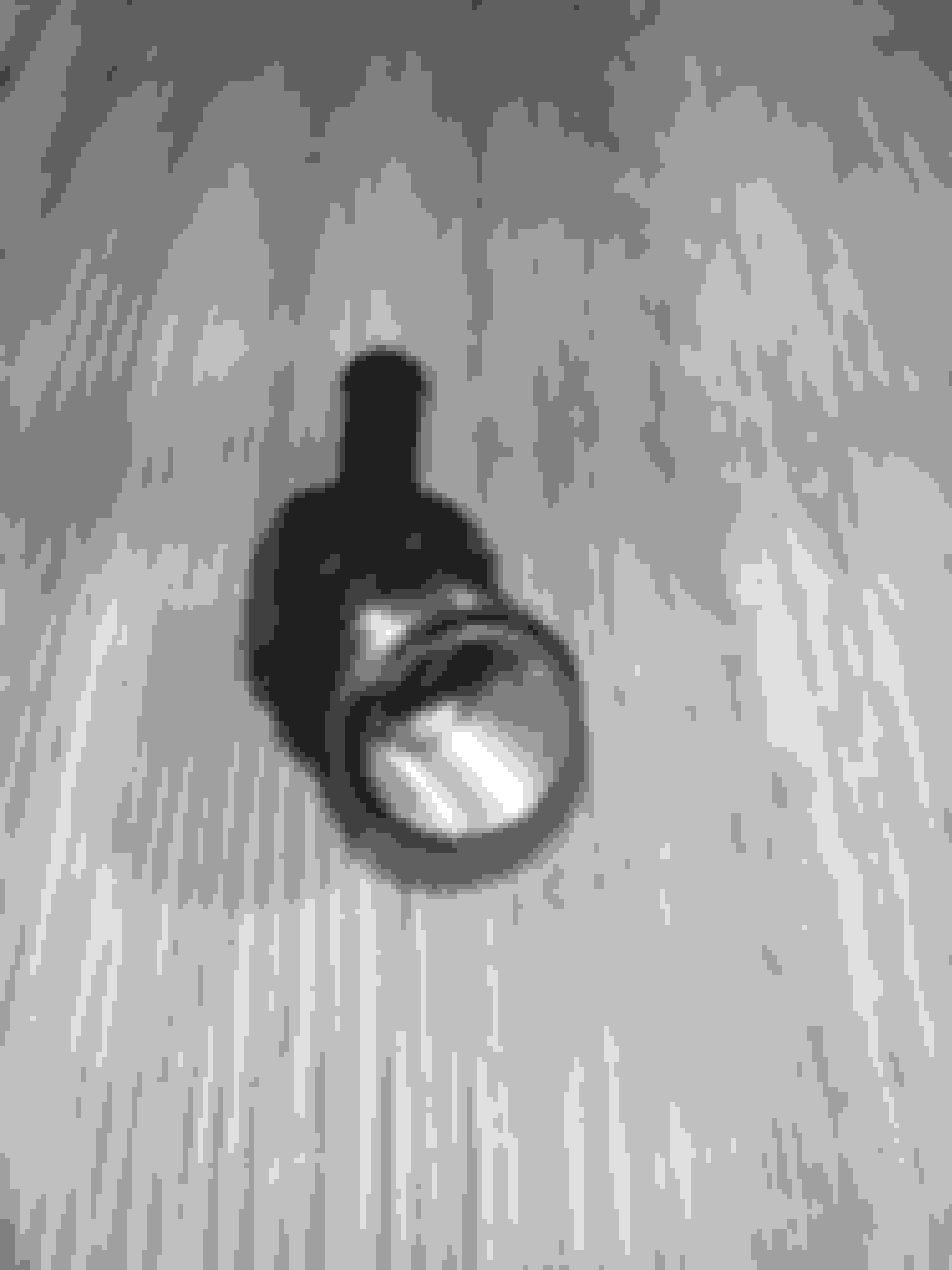
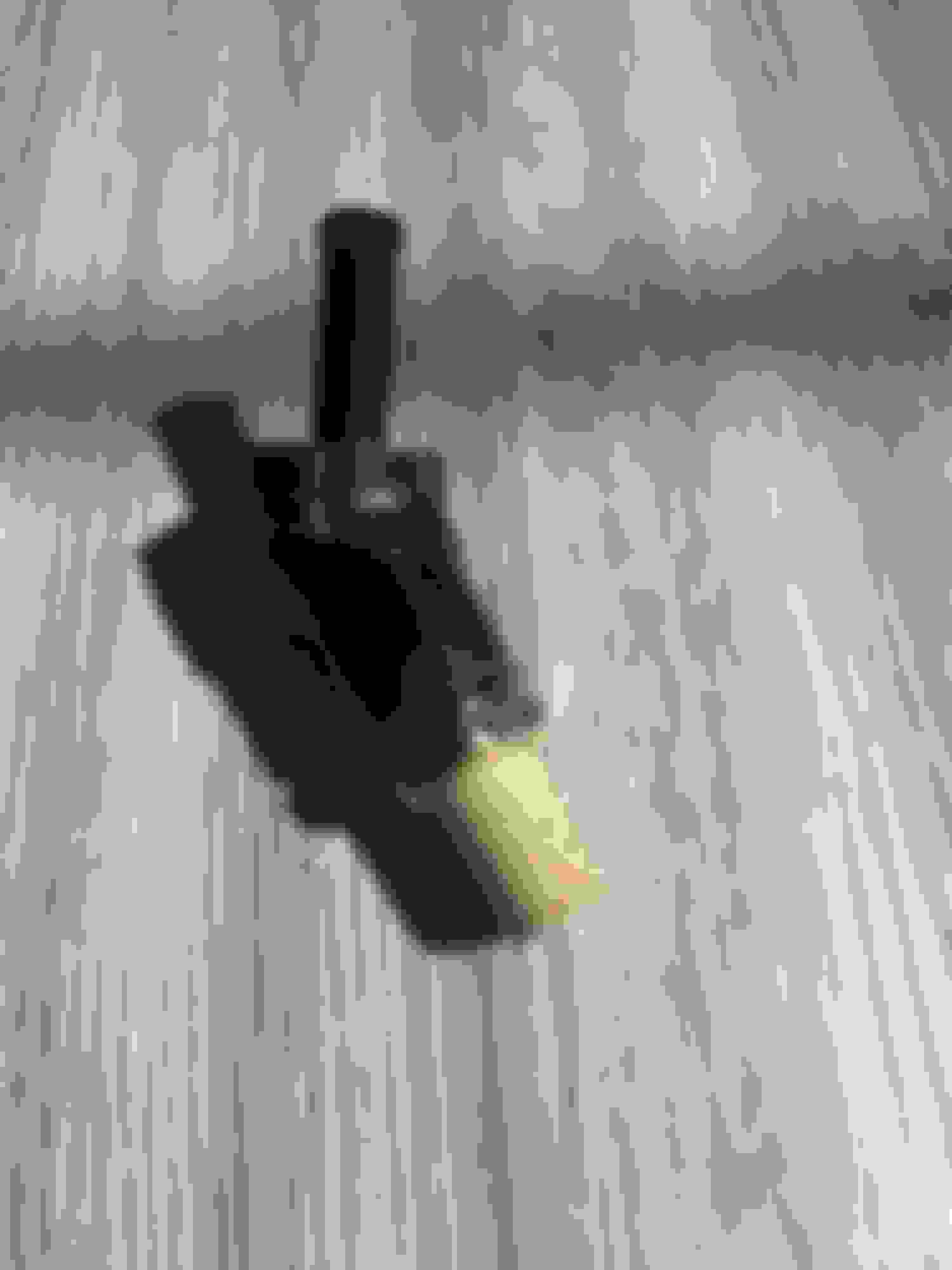
Finished the looking glass meter (made with real glass). Now moving on to some filtering material and a baffling tube, and I should have the most effective catch can one can make.
I didn't consider the high humidity; I'm also in Florida. Luckily, I'm not tracking the car yet. However, I think there's a second solution you can opt for. They make built-in heaters that utilize your coolant as heat (like our throttle bodies do from the factory, which helps melt ice off the butterfly valves in cold climates). If mounting it closer to the turbos is not an option, then I'd say you could T off the same hoses to the throttle bodies to feed into the inlet and outlet of the heater core for the AOS. You might have to modify one to keep it as a catch can since AOS routes oil back into your engine.
good thinking, it would be easy to do, you could use the Throttle body coolant loop.
however, its too complicated. especially for a track oriented car. its adding points of failure, and what is the benefit? a can of oily water?
good thinking, it would be easy to do, you could use the Throttle body coolant loop.
however, its too complicated. especially for a track oriented car. its adding points of failure, and what is the benefit? a can of oily water?
If you are using an aftermarket coolant temperature gauge that is typically tapped into the rear iron leading to the throttle body, you can eliminate that setup. Instead, modify the new heater core or manifold to accept a 1/8 PT fitting for measuring the coolant temperature there. This modification maintains the same number of potential failure points but only works if you already have an aftermarket coolant temperature gauge tapped into the rear iron. An added benefit is that it reduces condensation in the catch can, so it won't fill up as frequently.
.
I seen this product but the description lacks some detail. It's a dynamic plunger that adjusts the crankcase pressure to the manifold based on load. However, wouldn't it be better to not use the 'ORB PCV Valve' altogether and allow for maximum crankcase pressure relief. Why restrict it? The only advantage I can see is that it might prevent oil starvation by controlling the amount of vaporized oil that escapes through the valve but the OEM filler neck already does this with its long design and built-in chamber.
That's because depending on how the catch can system is setup it could cause a vacuum leak. For example, a vented catch can routed to the intake manifold can cause this, that's where this pcv valve comes in.
I wouldn't route a catch can to the manifold since you risk boosting your crankcase when you're in boost if that dynamic plunger fails. I'll have someone else run it first, lol, but I believe the vacuum off the turbo inlet is plenty. You don't need much vacuum in the crankcase and don't want to have too much vacuum, or it will decrease your oil pressure. This is from my own research so anyone can correct me if I'm wrong, I don't mind learning new things.
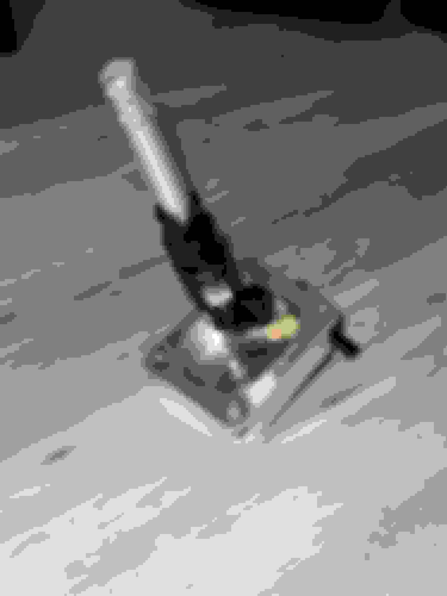
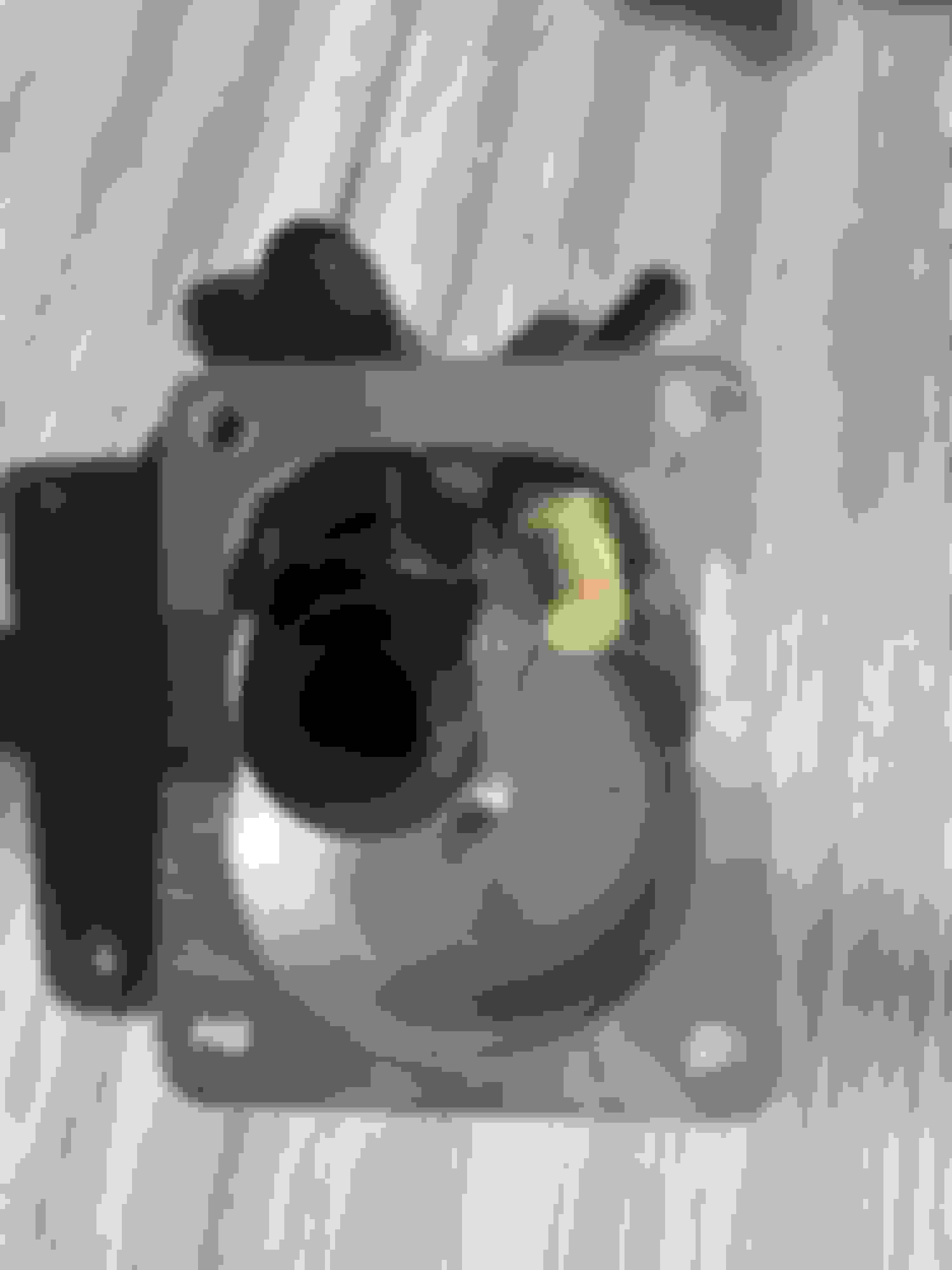
Also, below is my homemade oil catch can!
It can hold 300mL before oil covers the baffled tube. Luckily, my meter glass will tell me when it's at 300mL. I'll be adding a drain plug later, but this will do for now. It has everything those $300+ catch cans have: a brass filter, baffling, and stainless steel wool. My favorite feature is the metering glass that I made from computer open-loop hardware and a real glass tube. I had to use RTV with the -8AN "bulk head" threads to seal the can, if anyone was wondering in the future. I also use Earl's AN fittings, and the computer open-loop hardware was from EKWB. (Not sure if the O-rings can handle oil, but we'll see.)
The reason for adding to this thread will become apparent later.
I was having problems with a significant vacuum leak on my new engine rebuild on a fairly heavily modified twin step-up with KAI turbos. It's mostly a street car but has seen track days in the past. I found a partially severed silicone vacuum line from my original silicone hose job back from 2012, which was the best quality hose back then. The silicone was quite brittle and partially severed on a 30-40 degree bend on the vacuum side of the charge control line under the UIM. The other major vacuum leak was from a faulty stock PCV valve. This the second valve I had go bad in the last 10 years or so. This was almost completely locked open. Not good for idle with my catch can system going to my primary turbo inlet, which allowed this vacuum leak to occur. My current crankcase ventilation system has the stock PCV valve, with one end to the UIM and the other to an Excessive oil filler neck (stock like setup). Another line going from the oil filler neck to the input on a Mishimoto oil catch can and from the output on the catch can to the primary turbo inlet.
After much research, I have come up with a new aftermarket design for anyone needing true vacuum on the crankcase (BNR Stage 3 people, big blow by turbo setups, etc) or wishing to have some true vacuum on the crankcase, other than using the stock PCV valve setup or the "pseudo" vacuum of the primary turbo inlet setup or both of these in combination like I currently have.
Here is a hand drawn diagram of the proposed setup. The key to this setup is a high end fully adjustable PCV valve that can be tuned for minimal vacuum at idle and moderate vacuum on cruise or when the engine is more load bearing and seals completely shut, with no doubt, on boost and is reliable and can be cleaned, if necessary. This is the M/E Wagner PCV valve, which is shown below. Check out this PCV valve on their website and read about the technical stuff. Pretty cool that it can be adjusted for idle vacuum, to allow no material effect on our idle and can have a second stage for cruise or more load bearing times when we would like a little more vacuum on the crankcase.
With this proposed setup, the Wagner PVC valve would run from the UIM to the output of the oil catch can. The input of the oil catch can would be a line to the oil filler neck with the second port blocked. On the output line also, I would tee in a line to the primary turbo inlet, with a PCV type check valve on the line. Under idle and cruise, the Wagner PCV valve would draw a vacuum on the crankcase and the check valve to the primary turbo inlet would be closed, allowing the true vacuum to occur. Under boost, the Wagner PCV valve would close. If the crankcase starts to pressurize, this will open the check valve to the primary turbo inlet, allowing the pressure to be released. Any potential oil would be caught in the baffled oil catch can and not get to the UIM or the primary turbo inlet. Once off boost, the system returns to normal and the crankcase comes back into vacuum, relieving any leftover, built up pressure and closing the check valve to the primary turbo inlet.
What do you think? Did I miss something? Any red flags? Any improvements?
I had a long discussion with the designer of the M/E Wagner fully adjustable PCV valve. After this discussion and further research, I now have an updated design that on paper is far superior to my first design and would, I believe, benefit anyone using a catch can already or in need of a catch can to benefit their engine longevity, seal longevity, and potentially allow greater time between oil changes. In my discussion with Mr. Wagner, he was not familiar with our rotary engines but was very knowledgeable concerning crankcase ventilation in a piston engine, blow by gas contamination of engine oil, and forced air induction difficulty with pressurization of crankcases.
In my new design, under idle or at cruise during vacuum conditions, filtered fresh air from the primary turbo inlet or from any filtered fresh air source in a single turbo situation, under vacuum from the UIM through the PCV valve, would enter the lower oil neck fitting and then this fresh air would exit the oil neck from the upper fitting. The PCV valve is teed into the line going out the oil catch can and heading to the primary turbo inlet with a check valve between the PCV line and the primary turbo inlet in order to stop any vacuum loss through this line during normal conditions. Under normal driving conditions, this constant stream of lower velocity air would take any accumulating blow by gases, moisture, or any pressurization within the crankcase directly to the oil catch can. The degree of air flow through the system would be fully adjustable from the degree of vacuum set at the PCV valve hooked up to the UIM. The adjustable low vacuum could be set to alleviate any potential vacuum leak effect on the UIM and yet achieve desirable cleansing of the crankcase. Also, there is no way any major oil or other major contaminants would ever enter the engine through the UIM unless the catch can is full, is overwhelmed, or if someone used a poorer quality, non-baffled oil catch can. This is far superior to the standard PCV valve setup in a stock car, where all of these contaminants and oil can directly enter the engine through the UIM through the stock PCV valve. Also in the stock setup, major oil or other major contaminants can go directly to the primary turbo inlet through the stock connection to the primary turbo inlet, particularly if one has the stock PCV valve deleted or even has left in the stock PCV valve or has the 1995 style deleted PCV valve. Think about the constant cleansing of the oil filler neck/crankcase during idle, cruise, and more normal conditions. The oil dilution by fuel that is happening often under heavy load/boost and racing conditions can be purged to some degree when returning to normal operating conditions. That cleansing never occurs in typical closed oil catch can setups, that don't use true vacuum with a filtered fresh air source or in setups that use vented oil catch cans.
Under boost, the PCV valve closes, the high-quality minimal cracking pressure check valve from the primary turbo inlet to the oil filler neck closes, which forces oil or containments under any pressure directly to the oil catch can since the second check valve will open between the oil catch can and the primary turbo inlet. Again, the only way major oil or other major contaminants would ever enter the engine is if the oil catch can is full or overwhelmed under boost and then enters through the primary turbo inlet in a twin setup or out the filtered air source in a single turbo setup.
Lastly, one has to use high quality PCV-like check valves. These must be minimal cracking pressure valves since the degree of vacuum in the lines will be potentially small. A typical check valve has an opening pressure of almost 3 psi, which could be too high and allow the check valve to fail under low enough vacuum, since the Wagner PCV valve can be adjusted for very low vacuum. I found a minimal cracking pressure check valve with an opening pressure of just 0.04 psi, a max holding pressure of 300 psi, FKM seals, and high temperature capability from Improved Racing.
I will install this system on my car within the next few weeks. I will update after testing. This all potentially could again lead to greater engine longevity, seal longevity, and lengthened oil change intervals due to less blow by gas contamination of our engine oil with significant cost savings over time.
Mike
Updated Design Improved Racing minimal cracking pressure check valve