
Upgrade Your Alternator!!


Joined: May 2005
Posts: 3,243
Likes: 42
From: Kennewick, Washington
Still not going to increase capabilities how you think it will. If the resistance is the same between the two wires, then load will be divided equally.
So if there is more than 100 amps long enough, it will still pop your 50 amp fuse.
And if you just increase your overall fuse capability, you have to be sure that your wiring can handle the added load. As I stated before, fuses are there to protect the wiring. This is a safety matter. If a fuse is rated too high for the wire, then more amperage can transmitted than the wire can safely carry. It can overheat, melt, and possible catch fire.

Senior Member
Joined: Jul 2001
Posts: 483
Likes: 0
From: Sarasota FL/Ft Lauderdale
That is what I thought you were saying.
Having one 100a fuse and another 50a running in parallel is not how you properly increase a circuits ability to safely carry up to 150 amps. Nor properly protect it from an overload condition. It's not like 100 of the amps know to only try and go down one path while 50 of them go down the other.
I like to add a lead from the alternator post to the fuse box where the positive battery terminal is. The charging harness gets beat up from heat, age, and oil spilling on it from oil changes. This give the alternator another charging path to the battery.
Senior Member
Joined: Jul 2001
Posts: 483
Likes: 0
From: Sarasota FL/Ft Lauderdale
If some one is not familiar with basic electrical theories and concepts, I highly recommend that they do not attempt to modify their electrical system on their own. Either do some research on how to do it properly yourself or get a professional to do the work for you. And considering some of the **** electrical work that is passed off as "professionally done", I'd learn as much as you can so you'll have a good idea if you really got what you thought you'd paid for. :-)

If they're knowledgeable they should be able to. I had a gentleman in my home town of grand rapids mi rebuild several alternators for various cars over the years. He was cheap to....$40-60 for a complete rebuild/upgrade.
Doubling up on the wires is not how it's properly done. If for some odd reason you do choose to double up on your wiring for one circuit, either of the two wires individually should be capable of carrying the maximum potential amp load going to that circuit. Amps don't know that only X number of them should go down one path while the rest should take the other. And if either wire should develop added resistance for some reason, the amps are going to start taking the path of least resistance and perhaps overload that path. With potentially catastrophic results. Like your car burning to the ground.
If some one is not familiar with basic electrical theories and concepts, I highly recommend that they do not attempt to modify their electrical system on their own. Either do some research on how to do it properly yourself or get a professional to do the work for you. And considering some of the **** electrical work that is passed off as "professionally done", I'd learn as much as you can so you'll have a good idea if you really got what you thought you'd paid for. :-)
If some one is not familiar with basic electrical theories and concepts, I highly recommend that they do not attempt to modify their electrical system on their own. Either do some research on how to do it properly yourself or get a professional to do the work for you. And considering some of the **** electrical work that is passed off as "professionally done", I'd learn as much as you can so you'll have a good idea if you really got what you thought you'd paid for. :-)
Infact the factory wiring in the FD has circuits that have 2 seperate wires carrying current on the same circuit.
The main thing to remember is to make the wires the EXACT same length, once you do that it is a common electrical practice when working with high amp circuits.
Having said that, I would not run a circuit with a different amp rating as t-von does, that is not the correct way to do it and is infact bad electrical practice. He should upgrade the wiring on the circuit and use only one fuse but multiple wires if that is what he wants do do. Of course taking into account the current carrying capacity of the fuse block itself.
Basically if you really want to do it right the entire car should be rewired or just add a seperate fuse block for the extra components and upgrade the wiring from the alternator to the battery.
Senior Member
Joined: Jul 2001
Posts: 483
Likes: 0
From: Sarasota FL/Ft Lauderdale
What you are saying is not entirely correct.
Infact the factory wiring in the FD has circuits that have 2 seperate wires carrying current on the same circuit.
The main thing to remember is to make the wires the EXACT same length, once you do that it is a common electrical practice when working with high amp circuits.
Having said that, I would not run a circuit with a different amp rating as t-von does, that is not the correct way to do it and is infact bad electrical practice. He should upgrade the wiring on the circuit and use only one fuse but multiple wires if that is what he wants do do. Of course taking into account the current carrying capacity of the fuse block itself.
Basically if you really want to do it right the entire car should be rewired or just add a seperate fuse block for the extra components and upgrade the wiring from the alternator to the battery.
Out of curiosity what type of high amp capacity circuits use two smaller wires to split and share the amp load as opposed to one larger wire to handle the whole load? And why?
Thread Starter
Joined: Apr 2002
Posts: 6,719
Likes: 26
From: Midland Texas
Doubling up on the wires is not how it's properly done. If for some odd reason you do choose to double up on your wiring for one circuit, either of the two wires individually should be capable of carrying the maximum potential amp load going to that circuit. Amps don't know that only X number of them should go down one path while the rest should take the other. And if either wire should develop added resistance for some reason, the amps are going to start taking the path of least resistance and perhaps overload that path. With potentially catastrophic results. Like your car burning to the ground.
If some one is not familiar with basic electrical theories and concepts, I highly recommend that they do not attempt to modify their electrical system on their own. Either do some research on how to do it properly yourself or get a professional to do the work for you. And considering some of the **** electrical work that is passed off as "professionally done", I'd learn as much as you can so you'll have a good idea if you really got what you thought you'd paid for. :-)
I've had some classes and have successfully rewired my entire home remodel fully to add 200amp service so I have some knowledge. It also passed inspection. I can handle a/c .... d/c is child's play.

Heavy gauge wiring is just numerous strands bundled together in a single rubber coated line. Answer this question for me. If you take 2 gauge (which is rated at about 180amps depending on length) and a razor blade and cut out half the wire, rewrap that same wire into two individual separate strands and hook them together back on that same circuit, will it still carry 180 amps?
I guess Mazda didn't do it right because the factory wiring to the alternator is exactly done that way. It too has 2 single strands of small gauge wires joined together to carry the 90amp load at a common point. Removing anyone one of those strands cuts the load carrying in half.
Thread Starter
Joined: Apr 2002
Posts: 6,719
Likes: 26
From: Midland Texas
What you are saying is not entirely correct.
Infact the factory wiring in the FD has circuits that have 2 seperate wires carrying current on the same circuit.
The main thing to remember is to make the wires the EXACT same length, once you do that it is a common electrical practice when working with high amp circuits.
Having said that, I would not run a circuit with a different amp rating as t-von does, that is not the correct way to do it and is infact bad electrical practice. He should upgrade the wiring on the circuit and use only one fuse but multiple wires if that is what he wants do do. Of course taking into account the current carrying capacity of the fuse block itself.
Basically if you really want to do it right the entire car should be rewired or just add a seperate fuse block for the extra components and upgrade the wiring from the alternator to the battery.
In theory, I agree with t-von regarding wires in parallel. The total amount of copper is what matters, the electrons don't really care whether there are two separate bundles of copper or one bundle of copper, they will take the route with least resistance and so the current traveling through each wire be proportional to that wire's resistance. As long as the wires are routed in a safe manner, it's pretty unlikely one of your two wires are going to get cut or damaged to the point of leaving the other wire to carry all the current... how often do you worry that the original wire will get damaged or sliced in half?
In practice, you can't quite guarantee there will never be a short circuit or a broken wire, and the purpose of fuses are to burn first to protect the wire from burning. If you're going to run two wires in parallel but protect them with one fuse, the a fuse that is appropriate for protecting each wire individually is going to be about half the size of what should be used if you ran one larger wire. So the best practice would be to replace the undersized wires with single large wires, if you're able to.
By the way, I wouldn't consider the RX-7's wiring harness design to be a good example, for many reasons. There are quite a few high-power circuits that zig-zag back and forth across the car adding length (thereby weight and cost) without good reason... headlights and fuel pump are two examples. I'm also in strong disagreement with how many high-power circuits run through the ignition key. It's not a horrible design considering likely time and budget constraints. That said, there are quite a few things that would have been done differently if a knowledgeable wiring guy had spent an adequate amount of time designing the electrical system after the location for all the other mechanical parts in the car had been finalized.
Length would be far less important than the size of the wire I would think. It still gets back to the fact that if both wires are not rated to carry the full current load individually, you run the chance of at the very least burning out your wiring if one of those under rated wires fails or builds up extra resistance.
Out of curiosity what type of high amp capacity circuits use two smaller wires to split and share the amp load as opposed to one larger wire to handle the whole load? And why?
Out of curiosity what type of high amp capacity circuits use two smaller wires to split and share the amp load as opposed to one larger wire to handle the whole load? And why?
Not an automotive example but the building that I am currently working at in NYC has a 4,000 AMP service (yes, four thousand amps). It is impractical for the electrictions wiring up the transformers to use 1 single wire as it would be essentially impossible to work with so it is reduced to something like 8-10 wires and all are the SAME length. It serves the same purpose.
Mazda did it probably to keep the wire diameter smaller and allow the wire harness to flex and be able to make tighter radius bends.
Thx that's what I was thinking. I did originally try to find just the one 150 fuse but had no luck. So I just added the second. I may do some fuse testing to prove if it's safe or not. All I have to do is wire 2 circuits. 1 with a single 25amp fuse and another with 5 single 5amp fuses and see if the 5 fuse setup will blow at the time as the single fuse setup. Either way, if Mazda didn't think it was safe, they would have never added that empty spot to take and additional fuse. 2nd gen is the same way.
In theory, I agree with t-von regarding wires in parallel. The total amount of copper is what matters, the electrons don't really care whether there are two separate bundles of copper or one bundle of copper, they will take the route with least resistance and so the current traveling through each wire be proportional to that wire's resistance. As long as the wires are routed in a safe manner, it's pretty unlikely one of your two wires are going to get cut or damaged to the point of leaving the other wire to carry all the current... how often do you worry that the original wire will get damaged or sliced in half?
In practice, you can't quite guarantee there will never be a short circuit or a broken wire, and the purpose of fuses are to burn first to protect the wire from burning. If you're going to run two wires in parallel but protect them with one fuse, the a fuse that is appropriate for protecting each wire individually is going to be about half the size of what should be used if you ran one larger wire. So the best practice would be to replace the undersized wires with single large wires, if you're able to.
By the way, I wouldn't consider the RX-7's wiring harness design to be a good example, for many reasons. There are quite a few high-power circuits that zig-zag back and forth across the car adding length (thereby weight and cost) without good reason... headlights and fuel pump are two examples. I'm also in strong disagreement with how many high-power circuits run through the ignition key. It's not a horrible design considering likely time and budget constraints. That said, there are quite a few things that would have been done differently if a knowledgeable wiring guy had spent an adequate amount of time designing the electrical system after the location for all the other mechanical parts in the car had been finalized.
In practice, you can't quite guarantee there will never be a short circuit or a broken wire, and the purpose of fuses are to burn first to protect the wire from burning. If you're going to run two wires in parallel but protect them with one fuse, the a fuse that is appropriate for protecting each wire individually is going to be about half the size of what should be used if you ran one larger wire. So the best practice would be to replace the undersized wires with single large wires, if you're able to.
By the way, I wouldn't consider the RX-7's wiring harness design to be a good example, for many reasons. There are quite a few high-power circuits that zig-zag back and forth across the car adding length (thereby weight and cost) without good reason... headlights and fuel pump are two examples. I'm also in strong disagreement with how many high-power circuits run through the ignition key. It's not a horrible design considering likely time and budget constraints. That said, there are quite a few things that would have been done differently if a knowledgeable wiring guy had spent an adequate amount of time designing the electrical system after the location for all the other mechanical parts in the car had been finalized.
IMO, the stock harness is adequately designed though for a stock car. We who modify our cars are finding weakness in the factory wiring that the engineers do not have to worry about because they were not running the equipment we do. Also, it has been over 20 years since the FD was manufactured and electronic and wiring has come a long way since then.
Senior Member
Joined: Jul 2001
Posts: 483
Likes: 0
From: Sarasota FL/Ft Lauderdale
I've had some classes and have successfully rewired my entire home remodel fully to add 200amp service so I have some knowledge. It also passed inspection. I can handle a/c .... d/c is child's play.
Heavy gauge wiring is just numerous strands bundled together in a single rubber coated line. Answer this question for me. If you take 2 gauge (which is rated at about 180amps depending on length) and a razor blade and cut out half the wire, rewrap that same wire into two individual separate strands and hook them together back on that same circuit, will it still carry 180 amps?
I guess Mazda didn't do it right because the factory wiring to the alternator is exactly done that way. It too has 2 single strands of small gauge wires joined together to carry the 90amp load at a common point. Removing anyone one of those strands cuts the load carrying in half.
While I've never rewired a whole house, I have rewired a few boats in my time and work with DC and AC systems on a daily basis on the boats I run or engineer on for a living. The current boat I run has two main engines with 24v starting systems, two 40KW gensets with 12v starting systems, 2 100a 240v shore cords connected to boost transformers and 10 starting and house batteries. And none of these circuits is wired with doubled small wires feeding the same circuit. I guessing there is a good reason for that.
I'm also guessing when you rewired your house you didn't use any small doubled up wire runs to feed the same circuit connected to two circuit breakers each with a different trip rating to protect the same single circuit, correct?
As to your question, sure it may carry the load. But you seem to be missing or ignoring the point. If one of those two wires drops out or builds up extra resistance then the other wire could end up trying to carry more amps than it is rated for and burn up. Smaller wires also have more resistance so I don't see the point in wiring it that way.
I have noticed the two smaller wires at the alternator before. Question is, are they both going to the same place? If so I can't recall seeing any other alternators wired that way. Makes no sense to me to do it that way. And if there are feeding the same circuit it may be one of the reasons people are seeing voltage drops as our cars get older.
I may not be an electrical engineer but quite frankly you showed your ignorance of how basic electrical systems work when you thought that putting in one 100a and one 50a fuse in parallel in your fuse block is the proper way to protect it while increase it's load carrying capability when running an alternator capable of putting out 150 amps through it.
Thread Starter
Joined: Apr 2002
Posts: 6,719
Likes: 26
From: Midland Texas
Well currently on my alternator upgrade, I have a single 2 gauge wire that connects from the alternator to the battery/starter side of that fuse block. My battery also has 2 gauge that runs to the fuse panel from the storage bin. So on that side of the fuse block, my battery (and anything hooked directly to it) gets the full charging benefits of my upgraded alternator. Now I added that secondary fuse to the block because I thought it was needed to pass the full current capability over to the other side for the vehicle electrical. Now I know you can't pass 150amps through a 100 amp fuse so I added the 2nd fuse to create that additional path. I know I still need to upgrade that main line from the engine bay panel to the main under dash panel so that any additional electrical I add (not directly to the battery) has the energy it needs.
Thread Starter
Joined: Apr 2002
Posts: 6,719
Likes: 26
From: Midland Texas
AC and DC systems are not the same thing but both are "childs play" as long as the current is not flowing. :-)
While I've never rewired a whole house, I have rewired a few boats in my time and work with DC and AC systems on a daily basis on the boats I run or engineer on for a living. The current boat I run has two main engines with 24v starting systems, two 40KW gensets with 12v starting systems, 2 100a 240v shore cords connected to boost transformers and 10 starting and house batteries. And none of these circuits is wired with doubled small wires feeding the same circuit. I guessing there is a good reason for that.
I'm also guessing when you rewired your house you didn't use any small doubled up wire runs to feed the same circuit connected to two circuit breakers each with a different trip rating to protect the same single circuit, correct?
As to your question, sure it may carry the load. But you seem to be missing or ignoring the point. If one of those two wires drops out or builds up extra resistance then the other wire could end up trying to carry more amps than it is rated for and burn up. Smaller wires also have more resistance so I don't see the point in wiring it that way.
I have noticed the two smaller wires at the alternator before. Question is, are they both going to the same place? If so I can't recall seeing any other alternators wired that way. Makes no sense to me to do it that way. And if there are feeding the same circuit it may be one of the reasons people are seeing voltage drops as our cars get older.
I may not be an electrical engineer but quite frankly you showed your ignorance of how basic electrical systems work when you thought that putting in one 100a and one 50a fuse in parallel in your fuse block is the proper way to protect it while increase it's load carrying capability when running an alternator capable of putting out 150 amps through it.
On the house however, I did run the 3 wire romex yellow 12gauge 20amp from my parents 50amp electric stove connection to my newly installed circuit breaker box so I could have power through out the house as I did each rooms rewire. Even though I had a 50amp source, I knew I only had 20amps available to my box because of the 20amp wire used to connect it. So yea I had to be carefull on the number of items powered up during the remodel.
My inspector was in shock and told me he never seen a DYI done that well. You should have seen his eyes when I started turning on lights and how I had supplied the house with power. He actually asked me if I wanted a job if my career in the oil field took a turn. Lol!
Joined: May 2005
Posts: 3,243
Likes: 42
From: Kennewick, Washington
Ok. So if you have a 100 and a 50 in parallel. ..
That means you still only have 100 amps max throughput.
Anything over means the 50 amp fuse sees more than 50 amps. So 102 amps means each fuse sees 51 amps.
It's how it works. Stop trying to justify it.
That means you still only have 100 amps max throughput.
Anything over means the 50 amp fuse sees more than 50 amps. So 102 amps means each fuse sees 51 amps.
It's how it works. Stop trying to justify it.
Senior Member
Joined: Jul 2001
Posts: 483
Likes: 0
From: Sarasota FL/Ft Lauderdale
Thx that's what I was thinking. I did originally try to find just the one 150 fuse but had no luck. So I just added the second. I may do some fuse testing to prove if it's safe or not. All I have to do is wire 2 circuits. 1 with a single 25amp fuse and another with 5 single 5amp fuses and see if the 5 fuse setup will blow at the time as the single fuse setup. Either way, if Mazda didn't think it was safe, they would have never added that empty spot to take and additional fuse. 2nd gen is the same way.
Can you show us on this wiring diagram where that slot is for this extra fuse that runs parallel to the main fuse and feeds the same things as the main fuse? (Which based on the diagram should be a 120a not 100a.) Have you metered this extra fuse slot and confirmed that is does run parallel to the main feed wire and feed the same things?
http://wright-here.net/files/manuals...ng_Diagram.pdf
Thread Starter
Joined: Apr 2002
Posts: 6,719
Likes: 26
From: Midland Texas
Are we getting bent out of shape over the internet? That's not how it works!
Example:
If a 12 gauge wire can carry 40amps. 4 sets of them in parallel will carry 160amps. Right?
Fuses carry current just like wires do so if you take 4 40 amps fuses and wire them in parallel, you will be able to pass a total of 160amps over to the other side. The total output is much higher than what the individual fuses are rated for. Scotty305 said it best, "It's the total amount of copper that matters." Running both of those fuses in parallel give me a higher total amount so more current can pass through.
Another example if are running 100amps max through a wire rated for 100amps, that wire will get warm. If you add another wire capable of 50amps to that same wire, that original wire that was warm will cool off because you have added more cooper and more path of travel. You will now be able to run more current through those combined wires. Now that's how it works.
Thread Starter
Joined: Apr 2002
Posts: 6,719
Likes: 26
From: Midland Texas
You are kidding right!? But in case you are not, what are you going to use to bring the load up on these wires gradually and then cause the fuses to blow?
Can you show us on this wiring diagram where that slot is for this extra fuse that runs parallel to the main fuse and feeds the same things as the main fuse? (Which based on the diagram should be a 120a not 100a.) Have you metered this extra fuse slot and confirmed that is does run parallel to the main feed wire and feed the same things?
http://wright-here.net/files/manuals...ng_Diagram.pdf
I could easily wire up a fuel pump and start to dead end the pressure with a needle valve to manually raise the current. Then watch the load through an amp meter till the fuses start blowing.
A simple look at the fuse holder will show you what you need to see. Page 27. Look at the main fuse holder where the 120amp fuse is. Above that is the open slot that has a slash on the fuse cover. That's where I added my 50 amp.
I forgot the original fuse was 120amps. I blew mine a long time ago while doing my 20b swap and couldn't find a replacement at the local auto parts store. So I just stuck a 100 amp in their and forgot to put back the original over that time period. Oops!

Senior Member
Joined: Jul 2001
Posts: 483
Likes: 0
From: Sarasota FL/Ft Lauderdale
On the house however, I did run the 3 wire romex yellow 12gauge 20amp from my parents 50amp electric stove connection to my newly installed circuit breaker box so I could have power through out the house as I did each rooms rewire. Even though I had a 50amp source, I knew I only had 20amps available to my box because of the 20amp wire used to connect it. So yea I had to be carefull on the number of items powered up during the remodel. My inspector was in shock and told me he never seen a DYI done that well. You should have seen his eyes when I started turning on lights and how I had supplied the house with power. He actually asked me if I wanted a job if my career in the oil field took a turn. Lol!
My inspector was in shock and told me he never seen a DYI done that well. You should have seen his eyes when I started turning on lights and how I had supplied the house with power. He actually asked me if I wanted a job if my career in the oil field took a turn. Lol!
Are you sure he wasn't being sarcastic? And you need to stop talking now and go get some fire extinguishers to keep handy for the next time you decide to do any kind of wiring.
Thread Starter
Joined: Apr 2002
Posts: 6,719
Likes: 26
From: Midland Texas
I removed the starter lead so y'all can more clearly see the plate on the fuse holder that makes them parallel.

Also I made a mistake on my previous explanation of my wiring. My 2 gauge wire from my alternator actually connects to the opposite side of that fuse block (and not battery/starter side like I thought). So I added the extra fuse to pass more current back over to battery side.
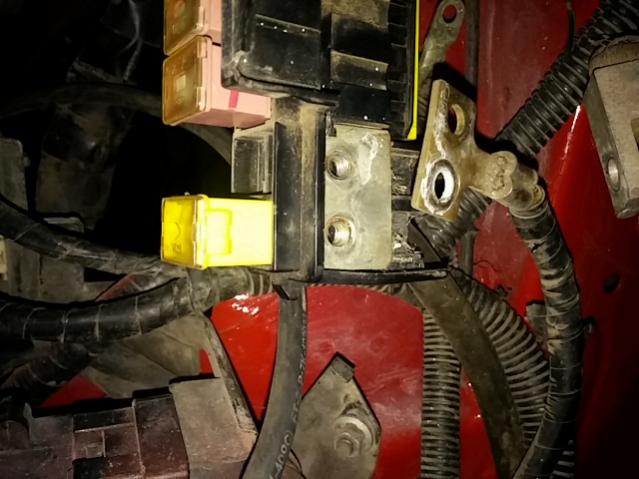
Also I made a mistake on my previous explanation of my wiring. My 2 gauge wire from my alternator actually connects to the opposite side of that fuse block (and not battery/starter side like I thought). So I added the extra fuse to pass more current back over to battery side.
Thread Starter
Joined: Apr 2002
Posts: 6,719
Likes: 26
From: Midland Texas
Um yes you do. Fuses carry current just like wires do. Two 40 amp wires in parallel will carry a 80amp total load. Fuses will do the same thing in parallel.
LOL no sarcasm house has been wired that way for almost a year till I finish and have the electrical company run the main feed. It's a one man project an why my 20b project isn't finished.
Senior Member
Joined: Jul 2001
Posts: 483
Likes: 0
From: Sarasota FL/Ft Lauderdale
Did you even look at how the wire/wires are attached to the block at that point? They all connected together. On one side you have a single wire bridged to both link holders and on the other you have two wires, one connected to each link slot but still bridged together. In effect you have just one path not two. Mazda left that fusible link slot empty for a very good reason. Not because you could add a second link and magically increase the current carrying capacity of the circuit at a later date but because it would be redundant, it's not needed. So adding a second fusible link into it does nothing, zilch, nada. It in no way increases the load carrying capacity of the circuit. It's a total waste of time and money!
You would do more good if you'd just put back in the correct 120a fusible link.
Senior Member
Joined: Jul 2001
Posts: 483
Likes: 0
From: Sarasota FL/Ft Lauderdale
As some one else pointed out, get back to us when 41 or more of those amps decides to go down one of those 40 amp wires or through one of those 40 amp fuses.