When you click on links to various merchants on this site and make a purchase, this can result in this site earning a commission. Affiliate programs and affiliations include, but are not limited to, the eBay Partner Network.
John no problem, let me know if/when you need to work through some of the wiring in the future.
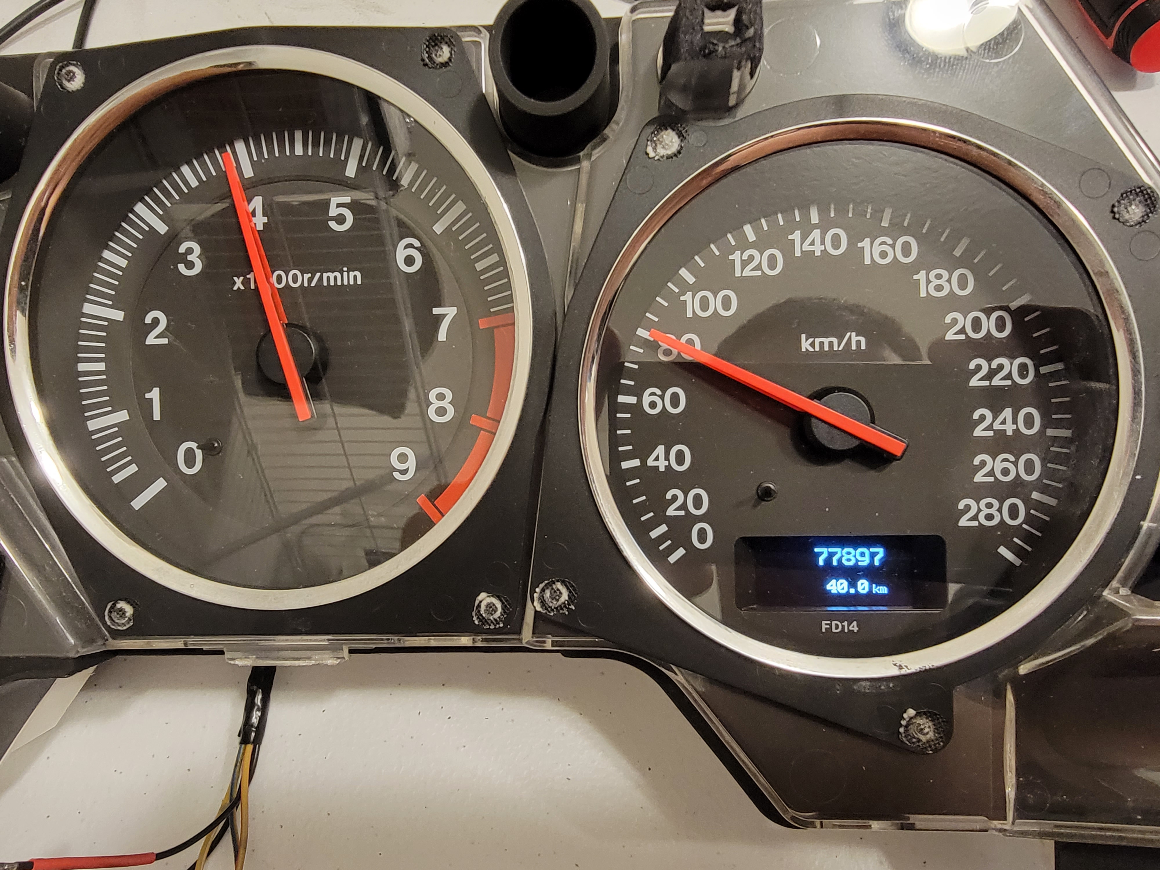
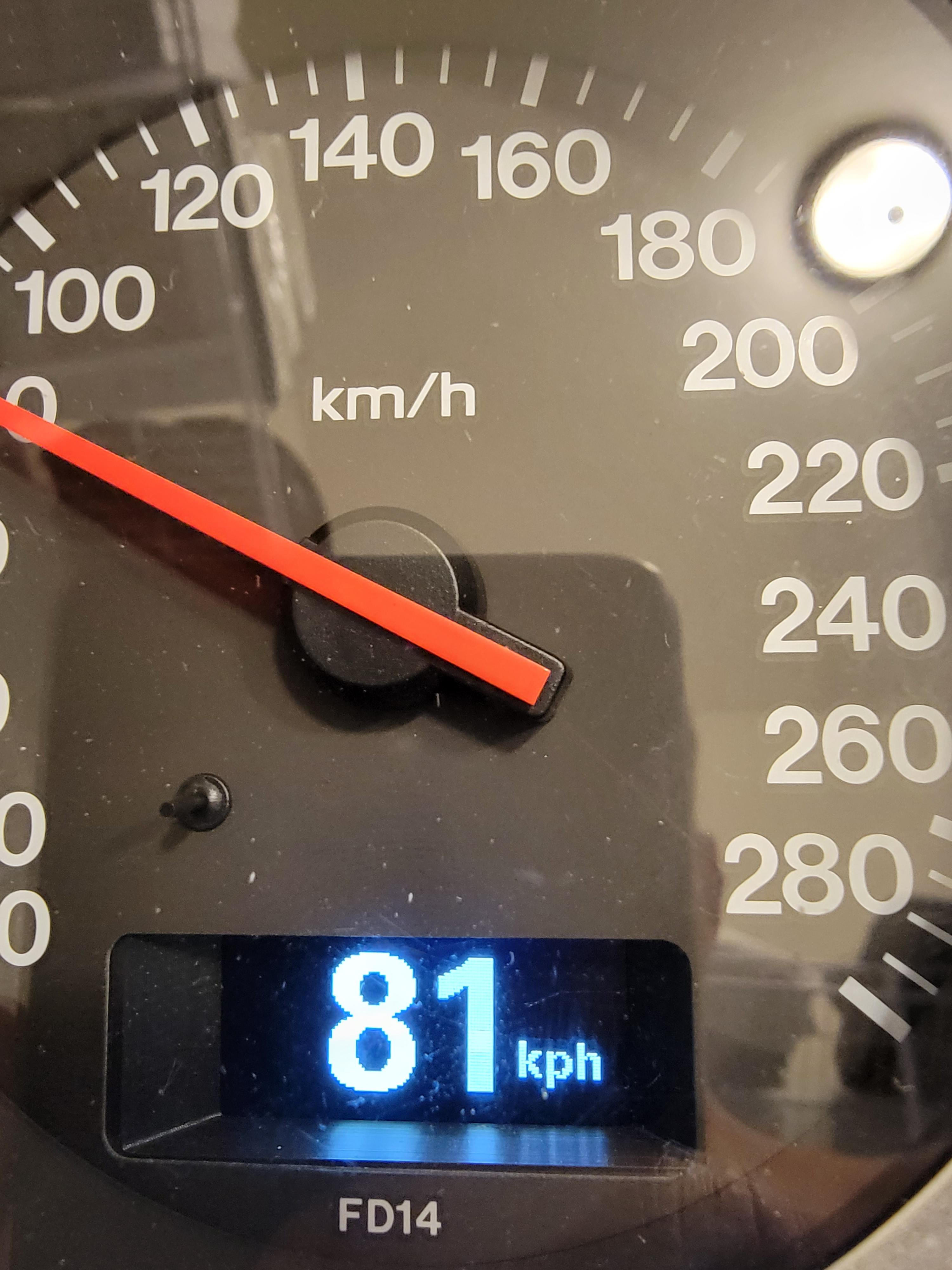
I have a bit of an update from ODO SPEEDO work ive been doing for a while in my free time....DRUM ROLL!!!!!!!! I have successfully hacked/built/programmed a working prototype for the odometer screen replacement with an OLED screen. I have the code reading from eeprom the mileage and displaying not only the ODO and TRIP values but also a digital read out of the speed coming directly from the speed sensor. I will be rolling this project out in phases:
Phase 1 a drop in replacement of the odometer screen:
- with better formatting than in my prototype picture here (the values are what's important at this stage)...Important achievements in this phase include, getting the speed signal cleanly and accurately represented, Having a robust storage algorithm for the odometer and trip values and making sure an interrupt triggers an Autowrite upon unexpected power off. All of this is near completion!
Phase 2 including other factory and aftermarket I/O:
- for easy viewing on the digital display...have had some requests for CAN bus interface for those with aftermarket ECU as well as the newly invented dual clutch transmission integration crowd to show selected gear, selected boost map etc.
Phase 3 Complete drop in replacement Digital speedometer:
- which would include all of the bells and whistles, remove the analog gauge completely, AND best of all plug directly into the existing flex board ribbon cable! (with of course of extra io connections for anything else)
I can't seem to get it to power on. Do I need to power all +'s and ground all -'s??? I get the coolant light, the fuel gauge sweeps to E, airbag light and illumination turns on but nothing else.
if the coolant light comes on then your odometer is on its probably just the backlight bulb. make sure you connect the ground to illuminate the odometer backlight.
In case anyone wants a replacement odometer that also includes a digita speed read out give me a shout. Check it out on instagram @geoff_pritchett for videos and other info.
Here's the backstory: First drive after lengthy rebuild and overhaul process. On my cluster the odometer when crazy... displayed random characters, would sometimes flash on and off, and the occasional speedometer jiggle over 60 mph.
Opened it up found C5 leaking and C1 looked ugly, so I replaced those and C12 while I was in there. Reassembled cluster and nothing, totally blank my guess is no power to the LCD screen.
Replaced same caps again because I had extras, still nothing.
Started tracing contacts with the multimeter and all seemed good, then I noticed some damage on the IC5 chip... an area I didn't get close to. Am I screwed here? should i go for a new cluster?
I've been trying to fix the blank odo on my 7. Replaced all the caps (except C15), ZD4, ZD5, ZD7 and TR7 (middle leg was broken).
After these changes, the odo works but with a strange startup - it shows "Predator"-like animations before showing the mileage and looking normal thereafter (see attached video).
But now after my changes speedo acts crazy (it had no problems before) - needle moves, jumps, bounces even when the key is in off position (see attached videos).
Has anyone experienced these symptoms? I'm kinda lost at this point and need your help/advice to move on with troubleshooting/fixing this thing. Any advice would be much appreciated)
@armans, Please post some pictures of your speedo board. Did you observe the correct polarity when replacing the capacitors and zener diodes? Pay close attention to the solder joints and show some pics of TR7.
The floating speedo needle could be the result of poor ground connections or issues with the ECU. What ECU are you using?
After repairing hundreds of these I've only seen the animations prior to displaying numbers once. Seemed like processor level issue. Was never able to remedy it.
Also floating speedo needle can't be due to the ecu. The signal comes directly from the speed sensor in 12v pulses 8 pulses per rotation of the vss. The signal comes in gets conditioned and the speedo board outputs a signal back to the ecu. To get a microprocessor to recognize the pulses a bank of diodes and a transistor chip is used. You will have to have a knowledge of how these chips work and measure on the board with a good multimeter to determine the issue. This can take a while as each board failure can be different.
@armans, Please post some pictures of your speedo board. Did you observe the correct polarity when replacing the capacitors and zener diodes? Pay close attention to the solder joints and show some pics of TR7.
The floating speedo needle could be the result of poor ground connections or issues with the ECU. What ECU are you using?
Here, please see attached photos, note that the floating needle happens with bench testing too (so ECU is not the problem here).
I made sure all the caps/zdiods are in correct polarity etc. I've used NTE123AP for TR7, note that it is significantly bigger in sizes than the original one. I think i may remove it and reinstall the original broken one and check if i get my pre-fix odo/speedo state back.
After repairing hundreds of these I've only seen the animations prior to displaying numbers once. Seemed like processor level issue. Was never able to remedy it.
Hi, Which processor is that? As far as i can tell, I specifically made sure i didnt touch processors
Ic5 is the onboard processor. Ic6 is an aircore motor driver that could be it but if your speedo worked fully prior to replacing components then it's probably fine. What components exactly did you try replacing specifically?
Ic5 is the onboard processor. Ic6 is an aircore motor driver that could be it but if your speedo worked fully prior to replacing components then it's probably fine. What components exactly did you try replacing specifically?
I've replaced zd4, zd5, zd7 (with 4.7v, 5.1v, 5.1v zdiodes respectively). Also tr7 (middle leg was broken), and all the caps except c15. Other than that, i took off zd3, cleaned the board and re-soldered same original zdiode.
I suspect the problem might be with the new diodes, doesn't seem caps would cause such symptoms, right?
Replace zd3 with a 5.1 and what transistor did you use for tr7? Gain is important here. There's not an exact replacement with exact gain for the c144 and that doesnt look like a c144. Not saying that's the issue. Also I havnt seen a video of the tach floating. Describe what you mean by float. Is it jumpy?


 and need your help/advice to move on with troubleshooting/fixing this thing. Any advice would be much appreciated)


