
track car radiator ducting project - many pics


track car radiator ducting project - many pics
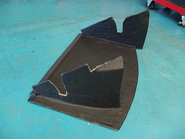
well, i did a hack job with aluminum sheets on the track car and though it was time to do a bit better job on the radiator ducting. I had a few weeks down time between track events and decieded to take the nose apart and try some stuff, basically i made a dedicated radiator duct that will replace the stock underpanel, eventually under that will be a full flat underpanel for, but here are the first run of pics on the rad ducting project:
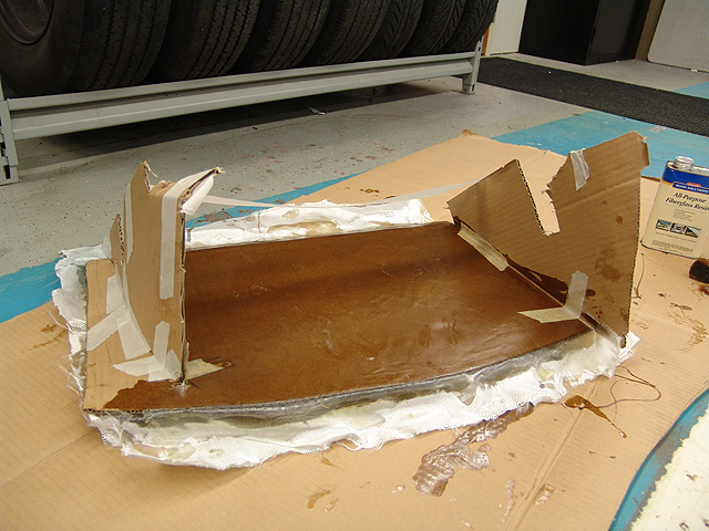
back side of cardboard mockup getting fiberglassed
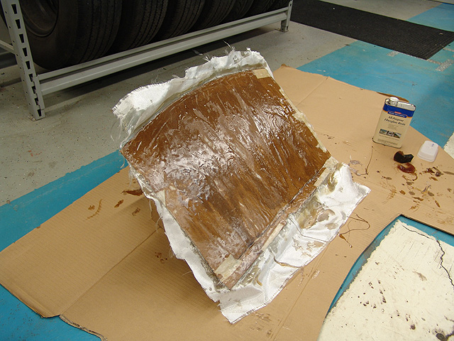
i just used cardboard to make the ducting mold and fiberglassed right ont he cardboard, making the cardboard become the 'skeleton' of the duct
a shot of it after i got the first layers of fiberglass on it

another shot fully glassed, it was a messy project :-)
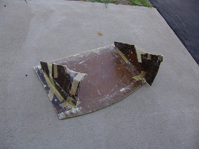
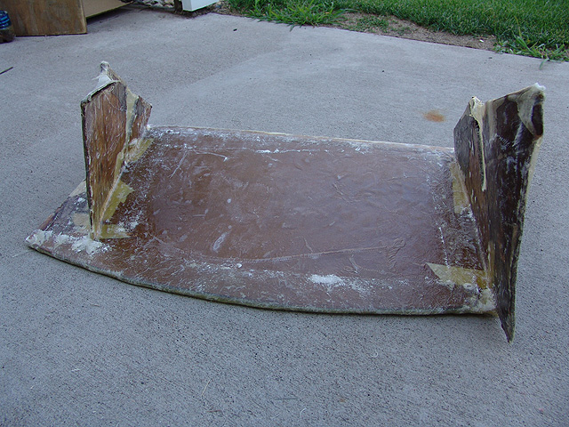
i sanded it down but i wasnt too good about making it perfectly smooth
after a first coat of black spray paint
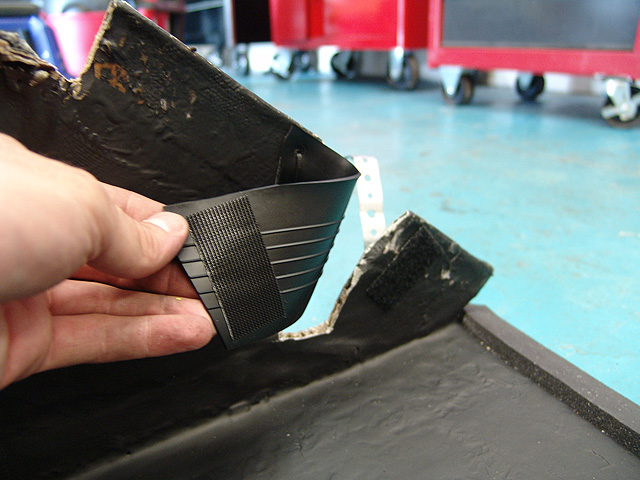
following a suggestion from the master (Noah at speedlabs) I used rubber flaps as the seal to the awkward power-stearing pipes that run in front of the radiator
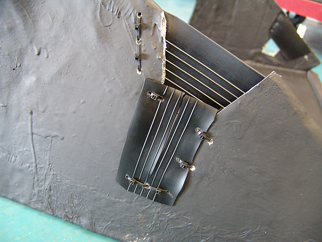
I used velcro to keep the 'free' side of the rubber flaps in place
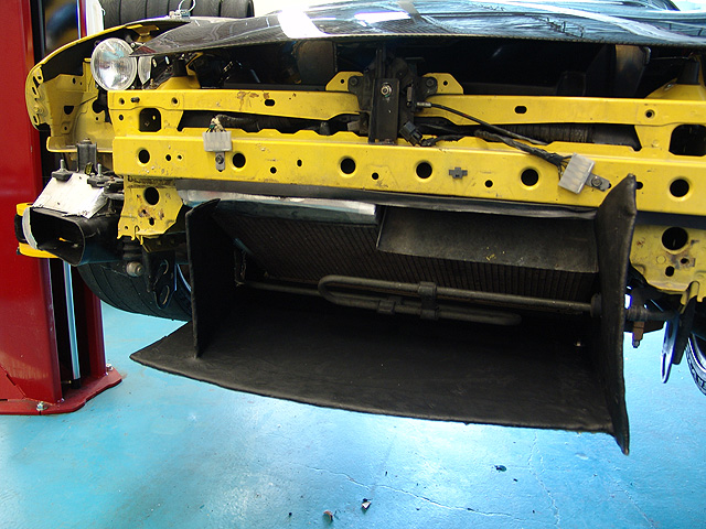
a test fit on the car, looking good so far :-)
back side of cardboard mockup getting fiberglassed
i just used cardboard to make the ducting mold and fiberglassed right ont he cardboard, making the cardboard become the 'skeleton' of the duct
a shot of it after i got the first layers of fiberglass on it
another shot fully glassed, it was a messy project :-)
i sanded it down but i wasnt too good about making it perfectly smooth
after a first coat of black spray paint
following a suggestion from the master (Noah at speedlabs) I used rubber flaps as the seal to the awkward power-stearing pipes that run in front of the radiator
I used velcro to keep the 'free' side of the rubber flaps in place
a test fit on the car, looking good so far :-)
Nice work Damian.
That actuially looks alot like the one I made for a customer. Stock 93 R1 bumper. Greddy FMIC and KOYO rad. I'll send you some pics of it.
Mine was fabbed out of 18 gauge steel. I am thinking of glassing it. Although I am confused as to how I would connect the uprights. Maybe you could give me an idea when you see mine. If you want to!
Now all you have to do is the air intake ducting!!!
On a side note. A few of the people I showed the scoop to during fabb, just laughed and made fun of the akward looks of my contraption. Well when it lowered his water temps by 25-30 degrees he shut up quickly. Seriously the temps were at 240 sitting in the shop after warm up. Dropped to 180 cruising and only have seen 195 with alot of "spirited" driving. Function over form anyday for me!!
Also what are you going to do for the top side? To keep the air from pushing out the top. I made a full plate for the gap between the Rad. and IC. But I am going to redue it for the whole bumper support area. ( cleaner look)
Last edited by BigIslandSevens; Jul 27, 2004 at 10:34 PM.
thanks BigIslandSevens :-)
>>Maybe you could give me an idea when you see mine. If you want to!
well, i attached the sides by using a strip of fiber glass that i layed down on a scrap piece of cardboard and 'painted' the resin on, then i layed it on the moild in the corners and used a foam brush (dipped in resin) to form the fiberglass strip into the courner, i did that a few times on each vertical 'fin' corner and that was that, pretty simple.
>>Now all you have to do is the air intake ducting!!!
well, its already build into this mold, i just dont have the final side wall up, it will make more sence in later pics
Originally Posted by Fatman0203
Damian care to do a write up on how to remove the front bumber =P? Or you used the shop manual?
hmm, well this is not a stock nose, its a mazdaspeed gtc and does not have stock rebar, popup light, et..... so for this car its real easy, just a few bolts and it comes off :-) i have never taken off the stock nose on my other car, so cant help ya there, sorry ;-)
Eats, Sleeps, Dreams Rotary
Joined: May 2003
Posts: 3,639
Likes: 0
From: MIA
Originally Posted by damian
hmm, well this is not a stock nose, its a mazdaspeed gtc and does not have stock rebar, popup light, et..... so for this car its real easy, just a few bolts and it comes off :-) i have never taken off the stock nose on my other car, so cant help ya there, sorry ;-)
Actually Ive been thinking of doing something similair to this for a long time. As a cold air box. I get massive amounts of boxes (cardboard) at my job, just the space time would be the only thing. Cool stuff damain, keep us updated on those temps.

Trending Topics
Originally Posted by obviousboy
are you running a fmic behind this??
Originally Posted by obviousboy
ahh i actually ment to say in this...
Damian,
Excellent job. I usually look at these threads with an eye towards what is wrong with the mod because so many mods screw up the car. I like the belly pan, I hope it is strong enough to hold up to high speed.
I LOVE the rubber around the PS line and the super duty velcro used to hold it down. That stuff kicks ***!
Great job!
thanks jeff :-)
>>I hope it is strong enough to hold up to high speed
it definetly should hold up, i used a few layers of fiber glass and the cardboard had a corrigated (sp?) center so it added a LOT of strength to it.
more pics to come as i get it further along...
>>I hope it is strong enough to hold up to high speed
it definetly should hold up, i used a few layers of fiber glass and the cardboard had a corrigated (sp?) center so it added a LOT of strength to it.
more pics to come as i get it further along...
Last edited by damian; Jul 28, 2004 at 01:46 AM.
they kinda are like that already, i getto-fabbed ducting with aluminum, sealed with metal plumbing tape, and have the wire mesh stuff, but it hooks to the nose, not the duct ;-)
Lives on the Forum
Joined: Feb 2001
Posts: 9,617
Likes: 8
From: Dallas
Originally Posted by EFS.O
for your oil coolers do something like this:
?????????????
Joined: Sep 2003
Posts: 512
Likes: 1
From: Greece
Originally Posted by DamonB
That is a TERRIBLE idea. You've just covered up most of the open duct so that you're no longer capable of getting much air actually through that mesh and into the cooler. I bet your void area is maybe 50%.
P.S the mesh is fairly large,its just the flash that makes it look small...:-)
Last edited by EFS.O; Jul 28, 2004 at 01:50 PM.
2/4 wheel cornering fiend
Joined: Nov 2002
Posts: 3,090
Likes: 3
From: Pasadena, CA
Originally Posted by DamonB
That is a TERRIBLE idea. You've just covered up most of the open duct so that you're no longer capable of getting much air actually through that mesh and into the cooler. I bet your void area is maybe 50%.

Photo Diety
Joined: Mar 2001
Posts: 2,311
Likes: 0
From: Florida
One should always use a mesh with a high void ratio. Usually this means an octagonal or square pattern. The larger the voids, the better. Using that style of grill mesh does indeed cut the airflow to more than half of the original. I'd get it off of there asap. If Greece is as hot as it is here in SW Florida, you're just asking for trouble 
Kent, any chance you guys are going to get a new MV1000 for a full road test vs. some of the other liter bikes? I liked Alan's writeup but he's an MV owner and therefore biased.
Kent, any chance you guys are going to get a new MV1000 for a full road test vs. some of the other liter bikes? I liked Alan's writeup but he's an MV owner and therefore biased.
Originally Posted by DamonB
That is a TERRIBLE idea. You've just covered up most of the open duct so that you're no longer capable of getting much air actually through that mesh and into the cooler. I bet your void area is maybe 50%.
Lives on the Forum
Joined: Feb 2001
Posts: 9,617
Likes: 8
From: Dallas
Originally Posted by pomanferrari
On the other hand, for convective cooling, you want turbulent air flow. That mesh sure looked like it will cause a hell of a turbulent air flow.
Convective cooling is for people who are trying to impress themselves with vocabulary.