
for those who have done the hose job...

Thread Starter
Senior Member
Joined: Jan 2002
Posts: 658
Likes: 0
From: Myanmar
im in the middle of doing the turbo simplification setup... i broke one selenoid, unbolted the ACV, i remove the ignition sys... but now i got stuck on the rat nest!! very difficult to remove the bolts!?! i used wd40 and it still wont budge...
i've got to have this car running by this Saturday so can any1 advice me on how to remove the nest? tanx in advance
i've got to have this car running by this Saturday
so can any1 advice me on how to remove the nest? tanx in advance
ok I'll tell you to do what everyone told me.... use a ratchet with a screw bit to get good force on the screws. They have loctite or somethin like that on them so if you stirp em out it sucks. just make sure you use a proper sized bit and put a lot of pressure on them before you turn them.


Rotary Freak
Joined: Jan 2002
Posts: 2,171
Likes: 1
From: Nashville Tn
Get an impack tool , you hold it on the screw and twist then hit it with a hammer. My mechanic uses it alot on motorcycles. Sears sells them and motorcycle shops sell them . I see three in his tool box with many types of bits. It work for him
Trending Topics
Full Member
Joined: Apr 2002
Posts: 145
Likes: 0
From: North Dakota
solenoids
i just removed all the crap underneath the intake mani i just did my vcuum lines last year in silicone they are still good will sell the rack with all the lines on it they are red have pics if wanted
Thread Starter
Senior Member
Joined: Jan 2002
Posts: 658
Likes: 0
From: Myanmar
gutted my main cat allready... and still waiting for my HKS downpipe... Wooohooo...
im not sure if they sell the belt that doesnt connect with the airpump (shorter belt)... can i just leave my airpump unpluged? will i have to block the holes from the airpump?
im not sure if they sell the belt that doesnt connect with the airpump (shorter belt)... can i just leave my airpump unpluged? will i have to block the holes from the airpump?
5yr member, joined 2001
Joined: Dec 2001
Posts: 908
Likes: 1
From: Marco Island, FL
Unplugging the airpump's grey electrical connector will cause the airpump pulley freewheel harmlessly. This is how I'm doing it right now. Go ahead and plug up the airpump if you are worried about dirt and such getting in and ruining the airpump. There is a belt that is the correct size for bypassing the airpump, but I do not know the size off the top of my head.
Thread Starter
Senior Member
Joined: Jan 2002
Posts: 658
Likes: 0
From: Myanmar
UPDATES...
*sigh* doing the vacuum hose job is such a tedious work!! I finally managed to take out the rat nest... i removed the solenoid rack...as well as the ACV.
now i stumble upon new questions... look at the diagram...
1. the hose behind the UIM, where is it going to?
2. where does the yellow hose from the y-pipe go to?
3. there are four solenoid left from the solenoid rack, can i just attach any color of the harness? the power supply i mean...
4. lastly... is there any way i can change the hoses behind the airpump (TCA, TPA and WCA) without taking out the airpump?? its very difficult to reach...
Thread Starter
Senior Member
Joined: Jan 2002
Posts: 658
Likes: 0
From: Myanmar
5yr member, joined 2001
Joined: Dec 2001
Posts: 908
Likes: 1
From: Marco Island, FL
#1: Are you talking about a vacuum hose nipple? Maybe it just gets capped, I can't remember. You'll probably figure it out. One of them goes to the MAP sensor, of course.
#2: See those 4 nipples on the top, front of the LIM? Those nipples go straight through the LIM. The (yellow-orange) y-pipe hose is the same color as the hoses going into the pressure chamber and check valve. The hose goes y-pipe -> LIM nipple -> check valve -> pressure chamber. Depending on your setup, it might be easier to skip the LIM nipple.
#3: I'm not sure what you're asking here. If you are putting the unused solenoids back on the connectors, then I would try and match them up to their original connecters. However, I don't think it will be a problem if you mix them up.
#4: I don't know. I didn't bother with those .
.
[edit]I dug up some threads on belt sizes for the air pump elimination[/edit]
https://www.rx7club.com/forum/showth...pump+belt+size
https://www.rx7club.com/forum/showth...pump+belt+size
#2: See those 4 nipples on the top, front of the LIM? Those nipples go straight through the LIM. The (yellow-orange) y-pipe hose is the same color as the hoses going into the pressure chamber and check valve. The hose goes y-pipe -> LIM nipple -> check valve -> pressure chamber. Depending on your setup, it might be easier to skip the LIM nipple.
#3: I'm not sure what you're asking here. If you are putting the unused solenoids back on the connectors, then I would try and match them up to their original connecters. However, I don't think it will be a problem if you mix them up.
#4: I don't know. I didn't bother with those
.[edit]I dug up some threads on belt sizes for the air pump elimination[/edit]
https://www.rx7club.com/forum/showth...pump+belt+size
https://www.rx7club.com/forum/showth...pump+belt+size
Last edited by JONSKI; Mar 18, 2003 at 03:45 PM.
Thread Starter
Senior Member
Joined: Jan 2002
Posts: 658
Likes: 0
From: Myanmar
Originally posted by JONSKI
#1: Are you talking about a vacuum hose nipple? Maybe it just gets capped, I can't remember. You'll probably figure it out. One of them goes to the MAP sensor, of course.
#2: See those 4 nipples on the top, front of the LIM? Those nipples go straight through the LIM. The (yellow-orange) y-pipe hose is the same color as the hoses going into the pressure chamber and check valve. The hose goes y-pipe -> LIM nipple -> check valve -> pressure chamber. Depending on your setup, it might be easier to skip the LIM nipple.
#3: I'm not sure what you're asking here. If you are putting the unused solenoids back on the connectors, then I would try and match them up to their original connecters. However, I don't think it will be a problem if you mix them up.
#4: I don't know. I didn't bother with those .
#1: Are you talking about a vacuum hose nipple? Maybe it just gets capped, I can't remember. You'll probably figure it out. One of them goes to the MAP sensor, of course.
#2: See those 4 nipples on the top, front of the LIM? Those nipples go straight through the LIM. The (yellow-orange) y-pipe hose is the same color as the hoses going into the pressure chamber and check valve. The hose goes y-pipe -> LIM nipple -> check valve -> pressure chamber. Depending on your setup, it might be easier to skip the LIM nipple.
#3: I'm not sure what you're asking here. If you are putting the unused solenoids back on the connectors, then I would try and match them up to their original connecters. However, I don't think it will be a problem if you mix them up.
#4: I don't know. I didn't bother with those
.tanx for the reply...
#1. i know one of the hose is the MAP sensor.. so that means i just cap the other two nipple...
#2. i think your wrong here... i have to diagram in front of me... one is the full color vacuum hose and the other is the simplified diagram...
From the full color vacuum hose, the hose from the y pipe is blue!!! but on the simplified is yellow!?! so im wondering y the yellow-orange hose doesnt connect to anything? should i just cap it off?? is that it?
5yr member, joined 2001
Joined: Dec 2001
Posts: 908
Likes: 1
From: Marco Island, FL
Originally posted by Cihuuy
tanx for the reply...
#1. i know one of the hose is the MAP sensor.. so that means i just cap the other two nipple...
#2. i think your wrong here... i have to diagram in front of me... one is the full color vacuum hose and the other is the simplified diagram...
From the full color vacuum hose, the hose from the y pipe is blue!!! but on the simplified is yellow!?! so im wondering y the yellow-orange hose doesnt connect to anything? should i just cap it off?? is that it?
First off, make sure you have the "good" colored hose diagram. I have it hosted right here:
http://www.rpi.edu/~skrzyj/rx7/93vachosescolor.jpg
#1. I agree. I just checked the complete diagram and there are three nipples on the firewall side of the UIM:
- ACV switching solenoid (C) (not used in the simplification, so cap it)
- EGR solenoid (D) (also not used in the simplification, so cap it)
- MAP sensor
#2. On Ribinette's site it says:
"11. The orange line that seems to go to nowhere goes to the upper intake manifold (it should be obvious, just thought I'd mention it before someone asked)."
(He means upper part of the lower intake manifold... Trust me.
 )
)On the complete vac hose diagram, look at the light blue hose starting from the y-pipe. This hose then goes to a check valve, and then to the pressure chamber. What this is designed to do is simply pressurize the pressure chamber during boost. This pressure is fed to the Turbo Control solenoid (E), which is then used to operate the Turbo Control Actuator. In other words, this hose from the y-pipe is an important part of your sequential turbo system. Now look at the simplified vac hose diagram. Look at the yellow-orange hose. Again, the pressure chamber is connected to a check valve and the Turbo Control solenoid (E). However, in this diagram, the check valve hose starts at a nipple on the LIM. On the other side of the LIM is the corresponding nipple that connects to the y-pipe. This nipple and the three below it all go straight through the LIM, meaning they do not connect to the intake ports. Previously, this nipple was used for the EGR, but since it was eliminated, the author of the picture decided to use it to connect the y-pipe to the pressure chamber. Why did he decide to do this? Because the person moved their pressure chamber underneath the LIM to clean up the engine bay (click the pic of my engine bay in my sig). So, if you are going to leave your pressure chamber in the stock position, then simply don't use the LIM nipple. If decide not to use the LIM nipples for your y-pipe -> pressure chamber connection, then you don't even need to cap them, because they only connect to eachother and no pressure will be lost.
Thread Starter
Senior Member
Joined: Jan 2002
Posts: 658
Likes: 0
From: Myanmar
wow... i actually understood what your saying!!! who ever did this simplification is a genius... hahaha Im should definitely make a write up abt this work... cz lots of ppl forgot to clearly mention the tools that are needed, gasket replacement, how to unpressurize the fuel system and how to take out that damn rat nest!!! *sigh*
anyways... im almost done wiv the vaccum hoses... havent change the TCA hoses as it is to far to reach... i may have to try from the underbody.. (???) and need to make myself a BOP asap!
Oh one more thing... i remember the person saying abt not having the pressure regulator in the diagram...as he had an after market fuel system or something... should i just cap it of? or it connects to something??
u've been a good help... TQ
who ever did this simplification is a genius... hahaha Im should definitely make a write up abt this work... cz lots of ppl forgot to clearly mention the tools that are needed, gasket replacement, how to unpressurize the fuel system and how to take out that damn rat nest!!! *sigh*anyways... im almost done wiv the vaccum hoses... havent change the TCA hoses as it is to far to reach... i may have to try from the underbody.. (???) and need to make myself a BOP asap!
Oh one more thing... i remember the person saying abt not having the pressure regulator in the diagram...as he had an after market fuel system or something... should i just cap it of? or it connects to something??
u've been a good help... TQ
Last edited by Cihuuy; Mar 19, 2003 at 11:59 AM.
5yr member, joined 2001
Joined: Dec 2001
Posts: 908
Likes: 1
From: Marco Island, FL
I didn't even try to get at the turbo actuator hoses. I wish I had, though. Just remember to transfer your boost pills from the old hoses to the new hoses and don't mix them up, because they are different sizes.
About the FPR (Fuel Pressure Regulator). Read the first note on Robinette's site carefully!
"You MUST leave the stock system intact OR add an aftermarket pressure regulator of some kind. For those not modifying their fuel system at this time, be SURE to have the FPR solenoid and lines attached well and correctly (failure of any of these parts could easily cause engine failure)."
In other words, put the FPR solenoid (A) back on its plug (orange) and connect its hoses to the proper locations. You'll need the complete vac hose diagram for this one. You'll see two aqua-blue hoses leaving the FPR solenoid (A), but it's hard to tell where they go. Here's a pic that should clear things up.
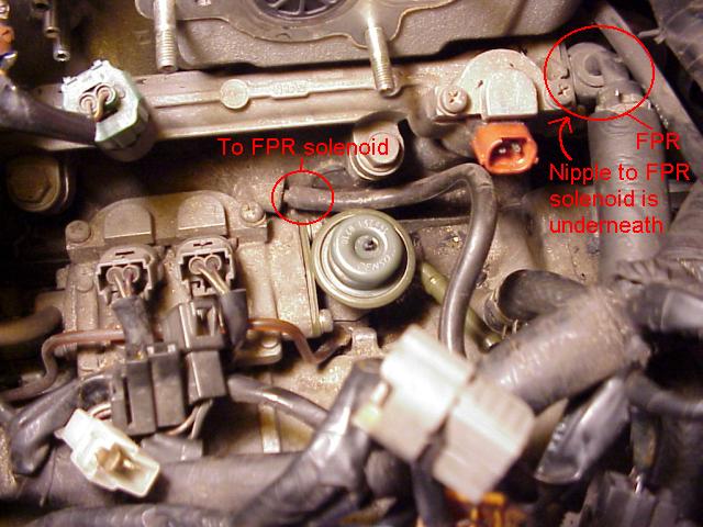
The LIM nipple goes to the back of the FPR solenoid (A) and the FPR nipple goes to the top of the FPR solenoid (A).
About the FPR (Fuel Pressure Regulator). Read the first note on Robinette's site carefully!
"You MUST leave the stock system intact OR add an aftermarket pressure regulator of some kind. For those not modifying their fuel system at this time, be SURE to have the FPR solenoid and lines attached well and correctly (failure of any of these parts could easily cause engine failure)."
In other words, put the FPR solenoid (A) back on its plug (orange) and connect its hoses to the proper locations. You'll need the complete vac hose diagram for this one. You'll see two aqua-blue hoses leaving the FPR solenoid (A), but it's hard to tell where they go. Here's a pic that should clear things up.
The LIM nipple goes to the back of the FPR solenoid (A) and the FPR nipple goes to the top of the FPR solenoid (A).
Thread Starter
Senior Member
Joined: Jan 2002
Posts: 658
Likes: 0
From: Myanmar
hmmm... im confused to which way is the front and the back of the solenoid... one side has the metal tube and the other has a plastic tube...
in short... by looking at the pix above...
small circle --> to FPR solenoid (the metal or plastic tube?)
LIM nipple --> to FPR solenoid (top)
sori for all of this question... dude
in short... by looking at the pix above...
small circle --> to FPR solenoid (the metal or plastic tube?)
LIM nipple --> to FPR solenoid (top)
sori for all of this question... dude
5yr member, joined 2001
Joined: Dec 2001
Posts: 908
Likes: 1
From: Marco Island, FL
The FPR solenoid, which came from the solenoid rack, (NOT the FPR, which is that black thing on the firewall side of the secondary injector rail) has two nipples and a ****.
Look at the FPR solenoid. The nipple underneath the electrical prongs goes to the diagonal nipple near the primary injector housing (the leftmost circle in the picture). Now feel underneath the FPR (not the FPR solenoid). That nipple on the bottom of the FPR connects to the upward-facing nipple (the one next to the ****) on the solenoid.
Look at the FPR solenoid. The nipple underneath the electrical prongs goes to the diagonal nipple near the primary injector housing (the leftmost circle in the picture). Now feel underneath the FPR (not the FPR solenoid). That nipple on the bottom of the FPR connects to the upward-facing nipple (the one next to the ****) on the solenoid.
Thread Starter
Senior Member
Joined: Jan 2002
Posts: 658
Likes: 0
From: Myanmar
i couldnt barely see anything under there, even wiv a flash light... but its all clear now... thanx all to you...
wonder why the person who made the simplification didnt clearly say abt this!?! i think he should update his web site... b4 some1 blow his engine... hehehe...
did you fix your boost pattern yet? from your sig...
wonder why the person who made the simplification didnt clearly say abt this!?! i think he should update his web site... b4 some1 blow his engine... hehehe...
did you fix your boost pattern yet? from your sig...
5yr member, joined 2001
Joined: Dec 2001
Posts: 908
Likes: 1
From: Marco Island, FL
I've got an even bigger problem than the poor boost pattern.
Champagne bubbles in the coolant .
.
Ugh. I figure I'll just do the copper block weld for now. When I've got a daily beater and a steady job I'm going to install a Malloy reman and do a 5-spd conversion.
Champagne bubbles in the coolant
. Ugh. I figure I'll just do the copper block weld for now. When I've got a daily beater and a steady job I'm going to install a Malloy reman and do a 5-spd conversion.
Joined: Oct 2002
Posts: 1,771
Likes: 0
From: Boulder, CO
SHITTY...
wow... so it was true then, we needed to keep the FPR solenoid connected....
Maybe this is why my engine wouldent FREAKING start, oh well, I already have the engine down to a bare block and im gona rebuild it...
how much can i get an aftermarket FPR?
wow... so it was true then, we needed to keep the FPR solenoid connected....
Maybe this is why my engine wouldent FREAKING start, oh well, I already have the engine down to a bare block and im gona rebuild it...
how much can i get an aftermarket FPR?