
stock ignition setup issue?


stock ignition setup issue?
Mind you I've searched and a couple other people I know have attempted to help me search this.
the REW doesn't have a place to adjust timing (that I have found). I checked it as it was one thing I spaced after reading in the FSM that timing is not to be adjusted. So today I checked it and its supposed to be
Trailing 20* ATDC
Leading 5* ATDC
My readings from my uber awesome timing light results...
Trailing 0*
Leading 25* BTDC
When I start to advance my timing light the little notch shows it's little white face from behind the water pump. Then once I hit 25* on my timing light it is lined up with the pointer on the front iron. Maybe I'm just confused? This definitely doesn't make much sense..
I double checked to make sure i had the right spark plug wires 3 times as that didnt seem right at all... So my timing light is one that you can adjust the timing so you can be super lazy or super accurate and look for 0* on the timing marks instead of trying to see "is that the 10* mark?!?!?". You set your timing light to 10* and look for 0* and done. So if you want to double check you put your timing light to 0* and look for the 10* mark, or at least on piston engines.
I also am 95% sure the spark plug wires are correctly hooked up to the ignition coil packs. Leading are on the same coil pack and each trailing plug wire have their own coil packs. Maybe this is why it runs like *** at idle.... Idk figured it wouldn't run the greatest "getting on it" but it laid down 266 whp and 250 ft.tq... With only exhaust and an intercooler upgrade. Kinda weird.... sooooo Anyone have any thoughts or ideas?!?
Last edited by 86boy; Jul 8, 2013 at 03:20 PM.
I even followed the FSM with checking the knock sensor (which is good) the MAP (which is also good). Then goes through a list of stuff as "input devices"
Input Devices:
E/L (electric load), P/S (Power Steering), A/C (Air Cond.), electric cooling fan
CAS (NE, G-signal)
Pressure Sensor (MAP correct?)
Throttle sensor
Neutral SW/Clutch SW (MT)
then it has "Others"
ECU terminal 3I voltage
The P/S, A/C, and electric cooling fans are all working. Looking through the FSM I've tested the pressure sensor if that is referring to the MAP, knock sensor, throttle sensor, and clutch switch. Those all tested out good. Not sure about the electic load controller, CAS or voltage on terminal 3I yet. Any ideas or am I on my own on this one? hahaha
Last edited by 86boy; Jul 11, 2013 at 10:18 AM.


OK, but its not matching up with what the FSM states about ignition timing. I understand its not adjustable, but something somewhere is causing all sorts of problems at idle with no CEL codes. I've gone through quite a bit of stuff already on this car and I still have an issue.
how would an adjustable timing light be incorrect when the ignition timing is fixed by jumping the pins in the diag connector? I'm kind of confused by that. My corolla has a wasted spark setup similar to the rx7 and I lock in the ignition timing, and i can check that all day long no problems. Only difference is there is no timing marks on the FDto ddouble check that. Maybe I'm confused with something I'm doing?
how would an adjustable timing light be incorrect when the ignition timing is fixed by jumping the pins in the diag connector? I'm kind of confused by that. My corolla has a wasted spark setup similar to the rx7 and I lock in the ignition timing, and i can check that all day long no problems. Only difference is there is no timing marks on the FDto ddouble check that. Maybe I'm confused with something I'm doing?
I won't claim to know anything about your timing light. What I will say is that with a $5 Harbor Freight one, your TRAILING should show up properly (mark lines up) if tested under FSM conditions.
So on an old rotary (before FD), there was a mark for the leading and trailing--yellow and red. On the FD, there's only a white mark for the trailing. You only need to deal with it if you have an ECU that is not stock and not a Power FC. A lot of FC engines have blown up due to mistakes with timing. Thankfully the FD is basically idiot proof if you use those two ECU's.
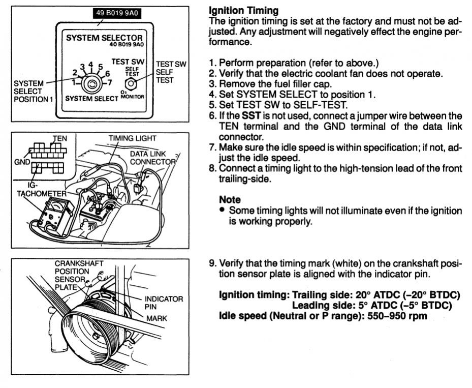
So basically, follow this procedure to the letter:
now compare to the FC procedure:
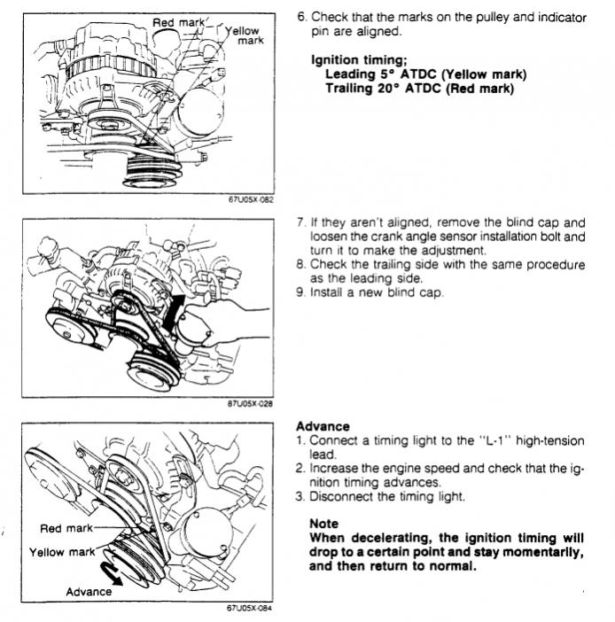
notice how there are two marks, and the procedure initially tells you to connect to the leading?
So on an old rotary (before FD), there was a mark for the leading and trailing--yellow and red. On the FD, there's only a white mark for the trailing. You only need to deal with it if you have an ECU that is not stock and not a Power FC. A lot of FC engines have blown up due to mistakes with timing. Thankfully the FD is basically idiot proof if you use those two ECU's.
So basically, follow this procedure to the letter:
now compare to the FC procedure:
notice how there are two marks, and the procedure initially tells you to connect to the leading?

Thread
Thread Starter
Forum
Replies
Last Post
befarrer
Microtech
3
Aug 22, 2015 05:52 PM