
Speedo signal wires

Thread Starter

Joined: May 2008
Posts: 4,389
Likes: 962
From: Stamford, CT
Speedo signal wires
I'm try to add a speed signal to me stand alone ECU
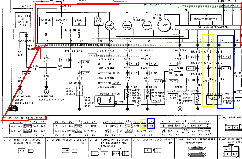
The speedo diagram in the FSM shows two wires going to the speed sensor, but doesn't detail which is the output. What should I hook to my ecu? Orange or green?
The speedo diagram in the FSM shows two wires going to the speed sensor, but doesn't detail which is the output. What should I hook to my ecu? Orange or green?


Thread Starter
Joined: May 2008
Posts: 4,389
Likes: 962
From: Stamford, CT
Looked up how to wire in the dakota digital box for speedo calibration of a T56 tranny on No-Rotors and they say to use the green wire, so that's what I'll do.
In the OEM setup, the speed sensor in the transmission connects directly to the dash cluster, not to the ECU. The dash cluster essentially duplicates the vehicle speed signal, sending a nice digital 0-5V signal to the stock ECU on pin 1M. If you still have the OEM dash installed, it will probably be easier to get the wire at the ECU connector.
In the wiring diagram, the ECU pin 1M is shown on page B-1d (Green/Red wire) and the Instrument cluster pin 3E is shown on pin C-1a (Green/Red wire).
In the wiring diagram, the ECU pin 1M is shown on page B-1d (Green/Red wire) and the Instrument cluster pin 3E is shown on pin C-1a (Green/Red wire).

Thread
Thread Starter
Forum
Replies
Last Post
The1Sun
New Member RX-7 Technical
5
Sep 15, 2015 04:45 PM
windom
Adaptronic Engine Mgmt - AUS
4
Sep 11, 2015 04:48 AM
The1Sun
1st Generation Specific (1979-1985)
0
Sep 7, 2015 10:21 PM