
Speed Sensor?

Thread Starter
Vagina Junction
Joined: Mar 2001
Posts: 1,838
Likes: 0
From: Seattle, WA
Speed Sensor?
Gonna hook up a GPS unit, and I need to get the vehicle speed sensor. I presume it's available at the ECU since the PowerFC gets it, but can anybody tell me which wire? And if it's a sine or square wave? Thanks!
~Tom
~Tom
Slam Pig
Joined: Dec 2002
Posts: 888
Likes: 0
From: New York
http://www.scuderiaciriani.com/
its on that site somewheres..tried looking real quick with no luck..but ive seen it
its on that site somewheres..tried looking real quick with no luck..but ive seen it
The auto->manual conversion guys dug through that stuff a while back. See if anything in there can help you out:
https://www.rx7club.com/forum/showth...4&pagenumber=3
https://www.rx7club.com/forum/showth...4&pagenumber=3
Super Snuggles
Joined: Feb 2001
Posts: 10,091
Likes: 34
From: Redmond, WA
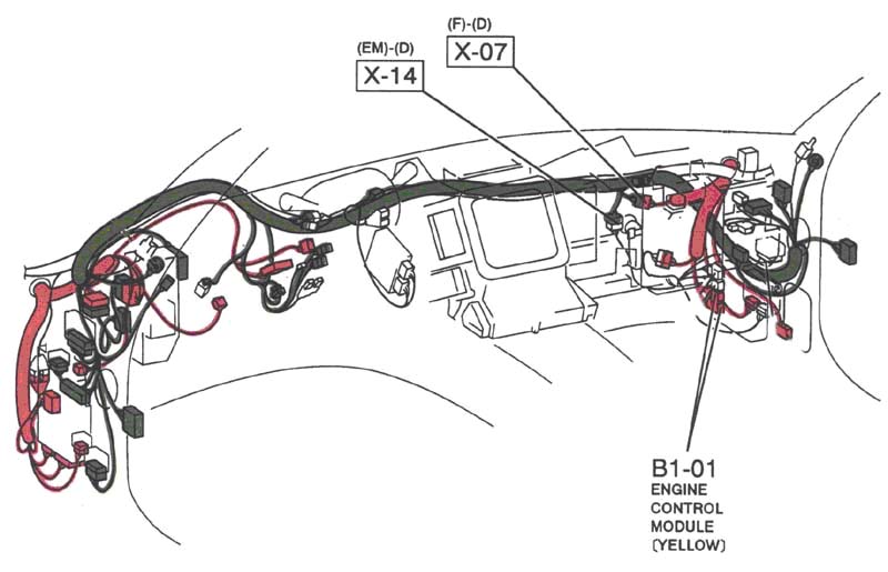
The orange wire on the emissions harness to dash connector (X-14 in the shop manual) is the ground connection from the speedometer comparator circuit to the vehicle speed sender (VSS). The green wire is the signal wire (VSS output) back to the speedometer.
The X-14 connector is tucked up under the dash on the passenger's side, behind (if memory serves, it's been a little while) the A/C section of the underdash crap. Be advised that it's a royal pain in the *** to get to.
Here's a little more information I posted in another thread...
The X-14 connector is tucked up under the dash on the passenger's side, behind (if memory serves, it's been a little while) the A/C section of the underdash crap. Be advised that it's a royal pain in the *** to get to.
Here's a little more information I posted in another thread...
The VSS sends out 8 AC pulses per driven gear rotation, according to my "service highlights" manual, and the analog speedometer is driven by a comparator circuit. The comparator receives the pulses which turn it on and off, and the computing element determines the amount of current to send to the cross coils based on the count. The current in the coils creates a magnetic field, moving the needle on the analog speedometer, indicating speed.
The U.S. speedometers are calibrated to ~8,200 pulses per minute @ 60 mph, and I suspect the Japanese (and Canadian, UK, and Aus) speedometers are also, or the equivalent in kph (96 kph), at any rate. Since the calibration shown for 100 kph (Canadian speedometers) is listed as ~8,490 pulses per minute, which is equivalent to ~62.5 mph/~8,500 ppm, that's the same as 60 mph/~8,200 ppm, which would indicate a standard VSS output for all cars.
The U.S. speedometers are calibrated to ~8,200 pulses per minute @ 60 mph, and I suspect the Japanese (and Canadian, UK, and Aus) speedometers are also, or the equivalent in kph (96 kph), at any rate. Since the calibration shown for 100 kph (Canadian speedometers) is listed as ~8,490 pulses per minute, which is equivalent to ~62.5 mph/~8,500 ppm, that's the same as 60 mph/~8,200 ppm, which would indicate a standard VSS output for all cars.
Last edited by jimlab; Feb 16, 2004 at 11:38 PM.
Trending Topics

Thread Starter
Vagina Junction
Joined: Mar 2001
Posts: 1,838
Likes: 0
From: Seattle, WA
Just a heads up for anybody looking for this sensor wire, an easier place to tap it is behind the guage cluster. I couldn't find X-14, so I began tracing wires with the Electrical Service Manual. The easiest place to access the signal is on the connector that is nearly dead center on the cluster. The wire color is Yellow/Red.
Super Snuggles
Joined: Feb 2001
Posts: 10,091
Likes: 34
From: Redmond, WA
Originally posted by Hyperite
Sounds like a sine wave, if the speedometer is analog. Is that right Jim?
Sounds like a sine wave, if the speedometer is analog. Is that right Jim?
Thanks, as always you're my ray of hope in an otherwise gloomy mess of wires
Super Snuggles
Joined: Feb 2001
Posts: 10,091
Likes: 34
From: Redmond, WA
Location of plug X-14 is under the dash on the passenger's side, behind the heater/air conditioning, on the firewall.
Plug X-14 wiring schematic.
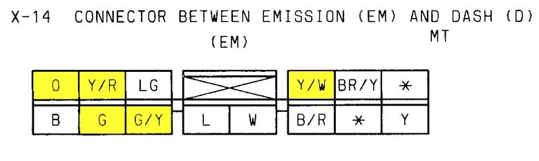
Below are the descriptions for the highlighted wires, and the shop manual pages (1995) that they appear on.
O - Orange
Page: Z-42
Description: VSS, ground
G - Green
Page: Z-42
Description: VSS, signal
Y/R - Yellow/red stripe
Page: Z-64
Description: Switched 12V+, from back-up light switch
G/Y - Green/yellow stripe
Page: Z-64
Description: 12V+ (15A - METER), to back-up light switch
Y/W - Yellow/white stripe
Page: Z-42
Description: Water temperature sender
Plug X-14 wiring schematic.
Below are the descriptions for the highlighted wires, and the shop manual pages (1995) that they appear on.
O - Orange
Page: Z-42
Description: VSS, ground
G - Green
Page: Z-42
Description: VSS, signal
Y/R - Yellow/red stripe
Page: Z-64
Description: Switched 12V+, from back-up light switch
G/Y - Green/yellow stripe
Page: Z-64
Description: 12V+ (15A - METER), to back-up light switch
Y/W - Yellow/white stripe
Page: Z-42
Description: Water temperature sender
Bringing back an old thread. What's the difference between the X-14 green wire versus the 1M, Vehicle Speed Sensor, pin on the ECU? I never realized that my ECU wasn't getting a proper VSS signal till I got my digital dash. Although my first mistake is that I needed a HALL signal whereas the RX7 had VR.
Joined: Nov 2001
Posts: 1,898
Likes: 13
From: Metairie, LA near new orleans
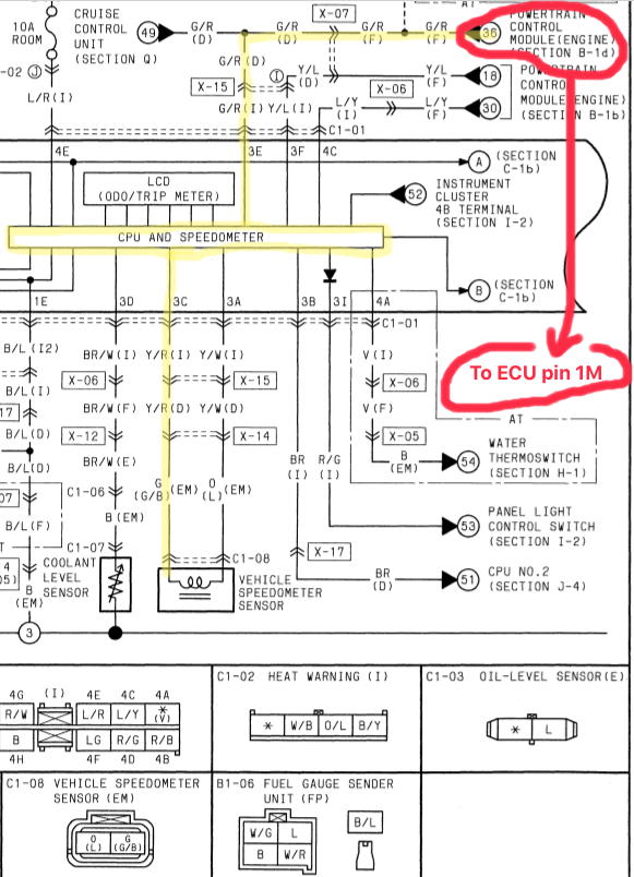
(G pin/wire color) goes to the X-14 connector (part of the EM-Emission harness) is coming directly from the speed sensor--this is the raw VR signal (analog). The B1-01 connector coming out of ECU (1M pin G/R wire color) goes to the X-07 connector (part of the F - Front harness) which is a signal that passes though the speedometer---I think this is also a VR signal (analog) as the FSM states the signal varies from 0-5V.
There is this thing that might help covert the VR to Hall signal: VR to Hall Converter | VEMS US
I'm not sure as this is beyond by circuits ability.

Ah I see. Thanks for clarifying. I think I'll tap the X14 plug then. I bought a VR conditioner board from Dual VR Conditioner Board V2.1. Hopefully this takes care of my Hall signal. Then I can finally put in my AEM CD-7. =)


Thread
Thread Starter
Forum
Replies
Last Post
The1Sun
New Member RX-7 Technical
5
Sep 15, 2015 04:45 PM
rx8volks
Canadian Forum
0
Sep 1, 2015 10:46 PM