
RX7 In-Dash Accurate Boost Gauge & A/F Meter +++ More!


Thread Starter
Junior Member
Joined: Jan 2003
Posts: 31
Likes: 0
From: Orange County, CA
I am going to need one to see even if it could be done. I have only 300z clusters that people have donated (bad just for examples) so either way I would need one. wish someone was in SoCAL. But Yes I could after I have made a prototype.
Thread Starter
Junior Member
Joined: Jan 2003
Posts: 31
Likes: 0
From: Orange County, CA
Please email me if you are in SoCAL near me and you can come to South Orange County. I assume you can get your dash out pretty easily, you can come over I can test your sensor, measure yotr dash and we can go from there. And what did you want A/F or Boost or Both?

Originally posted by ShokWaveRider
I am going to need one to see even if it could be done.
I am going to need one to see even if it could be done.
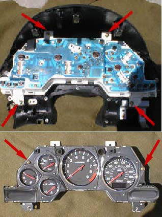
here is a pic of the one-piece circuit board
Last edited by ISUposs; Jan 20, 2003 at 07:59 PM.
Thread Starter
Junior Member
Joined: Jan 2003
Posts: 31
Likes: 0
From: Orange County, CA
There is a lot of room behind the tach for something can have you seen behind it? We may have to put the A/F stand alone.
Is this yours, can you take the tach dial off?
Regards,
Is this yours, can you take the tach dial off?
Regards,
boost deprived
Joined: May 2002
Posts: 152
Likes: 0
From: sioux city, IA
Originally posted by ISUposs
good luck guys, but it probably isn't going to be easy at all to get it to work right.
here is a pic of the one-piece circuit board
good luck guys, but it probably isn't going to be easy at all to get it to work right.
here is a pic of the one-piece circuit board
looking at that pic though, maybe Ian could incorporate
the half-inch tall LED display/guage into the lower right bay where the seatbelt light, battery charge light, e-brake light and high-beam light is?
that might be kind of pointless though, having to look down there to read it.
Thread Starter
Junior Member
Joined: Jan 2003
Posts: 31
Likes: 0
From: Orange County, CA
If it is then you are out of luck you should see the space in the 300z tach. check this post on the Z forum. Sorry about the lack of a link.
http://www.twinturbo.net/net/viewmsg...&msg_id=764639
http://www.twinturbo.net/net/viewmsg...&msg_id=764639
hey guys, don't give up hope. I COULD be wrong you know 
It's been a little while since I took my dash apart so i don't remember if there is no room for sure. it just seems like that was the case.
It's been a little while since I took my dash apart so i don't remember if there is no room for sure. it just seems like that was the case.

Senior Member
Joined: Mar 2001
Posts: 260
Likes: 0
From: Kannappolis, NC
Ian - glad to see you made it over here (I was the one on the Supra forum).
Several folks mentioned wanting to be able to use wideband. The great thing about Ian's idea is that you can use just about anything that uses LEDs as a display. Says you have a wideband unit that uses 20 LEDs vice 10 - so you install 20 LEDs and intercept where the original unit was sending the voltages to the LEDs to your new LEDs. (Sounds more complicated than it really is).
Ian - since you're obviously pretty good with circuits, here's info on building your own wideband circuit: http://www.diy-efi.org/diy_efi/projects/diy_wb/ - I'm sure you can convert the voltages to LED driver signals
I also photoshopped what our gauge would look like with your idea implemented - dunno if it'll be possible though since its flat:

I don't think the tick marks being different on the 94+ will make any difference seeing as how the boost LEDs are arranged in a semi-circle independent to the layout of the markings on the tach - I would imagine the circuit board behind is laid out exactly the same way.
Worst case, this idea could be implemented into the gauge cover/shield hood area.
Several folks mentioned wanting to be able to use wideband. The great thing about Ian's idea is that you can use just about anything that uses LEDs as a display. Says you have a wideband unit that uses 20 LEDs vice 10 - so you install 20 LEDs and intercept where the original unit was sending the voltages to the LEDs to your new LEDs. (Sounds more complicated than it really is).
Ian - since you're obviously pretty good with circuits, here's info on building your own wideband circuit: http://www.diy-efi.org/diy_efi/projects/diy_wb/ - I'm sure you can convert the voltages to LED driver signals
I also photoshopped what our gauge would look like with your idea implemented - dunno if it'll be possible though since its flat:
I don't think the tick marks being different on the 94+ will make any difference seeing as how the boost LEDs are arranged in a semi-circle independent to the layout of the markings on the tach - I would imagine the circuit board behind is laid out exactly the same way.
Worst case, this idea could be implemented into the gauge cover/shield hood area.
Thread Starter
Junior Member
Joined: Jan 2003
Posts: 31
Likes: 0
From: Orange County, CA
What a great looking mock up!
That is a great overlay! I wish I was good at Photoshop. The Key is to get behind it to see if there is room for the wiring.
I looks good doesn't it? LED Colorsare optional you can have them all clear until they are illuminated, clear LEDs are brighter though.
I took a look at that circuit. It incorporates a heater control. Wide Band would need either a Real Numerical Digital Display (which I have). There is a lot of circuitry involves which makes the PCB quite large and too big for a project PCB. More thought would have to go into it. But it would be doable. Probably best left standalone though as it would be VERY annoying to have on permanently I would think. I turn my 10 LED version off most of the time anyway. Especially when there are so many other useful gauges that can be "stuck" in there. Like Fuel And Water Injector Duty, Voltage etc. Here is a template I did for a 300zx TT Nissan that I am cutting steel on as we speak.

The Different numbers are different boost options and the water, Fuel and voltage are for the speedo. This template is for both the speedo and the tach fabrication. But you should get the idea.
SWR
I looks good doesn't it? LED Colorsare optional you can have them all clear until they are illuminated, clear LEDs are brighter though.
I took a look at that circuit. It incorporates a heater control. Wide Band would need either a Real Numerical Digital Display (which I have). There is a lot of circuitry involves which makes the PCB quite large and too big for a project PCB. More thought would have to go into it. But it would be doable. Probably best left standalone though as it would be VERY annoying to have on permanently I would think. I turn my 10 LED version off most of the time anyway. Especially when there are so many other useful gauges that can be "stuck" in there. Like Fuel And Water Injector Duty, Voltage etc. Here is a template I did for a 300zx TT Nissan that I am cutting steel on as we speak.
The Different numbers are different boost options and the water, Fuel and voltage are for the speedo. This template is for both the speedo and the tach fabrication. But you should get the idea.
SWR

Thread
Thread Starter
Forum
Replies
Last Post
streetlegal?
New Member RX-7 Technical
13
Mar 17, 2022 02:46 PM