
PWM adapter PCB for gauges, radio, etc


PWM adapter PCB for gauges, radio, etc
Just finished testing these, so I figured I'd share with the rest of you crazy lot.
Back in 2006, nashermang posted a quick little circuit for adapting the RX7's PWM to a more standard variable voltage.
It works great in my testing, and I've got it hooked up to both my radio and Defi gauges without issue. It should be noted though that this circuit can handle very little actual power, so it may not work with very simple devices (though you'll likely find anything this wont' work with, you can just drive straight from the stock circuitry)
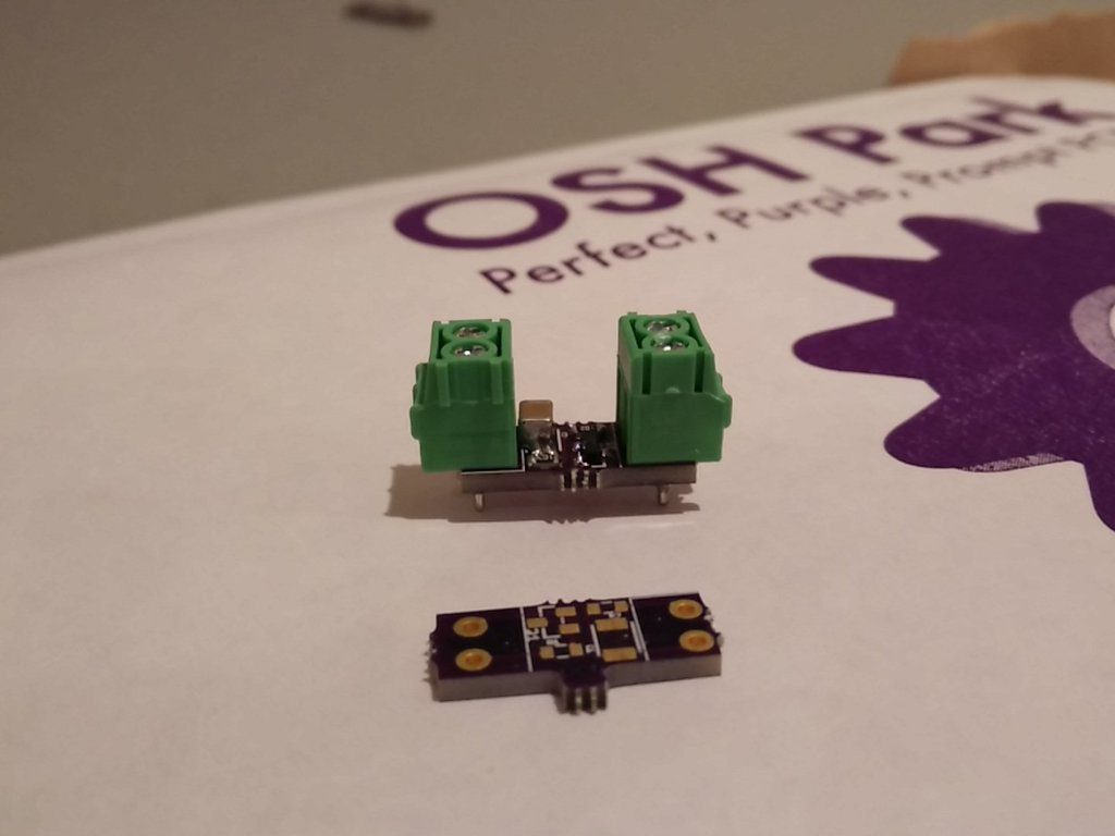
This is a fairly simple circuit, and you can certainly solder this in protoboard or just straight point to point really. But I like clean installs so I went ahead and worked up a PCB.

You can grab the eagle files here: http://comeonandsl.am/dev/FD_Dimmer_0805.zip
The linked version is slightly smaller, as you can just solder the terminal blocks on the bottom if you want to use them. For a permanent install I would skip them entirely and just solder, then you can cover the entire board with a piece of heatshrink. If there's interest, I can work up a larger through-hole version for you people who are afraid of SMT parts; but I stuck with larger package sizes so it would be easy to hand solder. Resistors are 0805, and the transistor is a SOT23. You can also solder these in a reflow oven, or a skillet. I hand soldered this one since I was too lazy to break out the paste for four components.
OSHPark will run you a set of 3 boards for dollars, and you can get the individual parts from mouser for less than $10 shipped. If some enterprising forum member wants to do a batch of these, feel free. Shipping was almost half of the actual cost in a single run, so they scale well if you want to order in any kind of volume.
Parts list:
Operation: Pull the PWM high and low pins into the PWM input side. The other end has a chassis ground and your PWM out. In my install I pulled the PWM pins from the radio harness, as both were already broken out in my harness. The VOUT pin will spit out between ~10.5 volts all the way down to 0, depending on the dimmer position.
Back in 2006, nashermang posted a quick little circuit for adapting the RX7's PWM to a more standard variable voltage.
It works great in my testing, and I've got it hooked up to both my radio and Defi gauges without issue. It should be noted though that this circuit can handle very little actual power, so it may not work with very simple devices (though you'll likely find anything this wont' work with, you can just drive straight from the stock circuitry)
This is a fairly simple circuit, and you can certainly solder this in protoboard or just straight point to point really. But I like clean installs so I went ahead and worked up a PCB.
You can grab the eagle files here: http://comeonandsl.am/dev/FD_Dimmer_0805.zip
The linked version is slightly smaller, as you can just solder the terminal blocks on the bottom if you want to use them. For a permanent install I would skip them entirely and just solder, then you can cover the entire board with a piece of heatshrink. If there's interest, I can work up a larger through-hole version for you people who are afraid of SMT parts; but I stuck with larger package sizes so it would be easy to hand solder. Resistors are 0805, and the transistor is a SOT23. You can also solder these in a reflow oven, or a skillet. I hand soldered this one since I was too lazy to break out the paste for four components.
OSHPark will run you a set of 3 boards for dollars, and you can get the individual parts from mouser for less than $10 shipped. If some enterprising forum member wants to do a batch of these, feel free. Shipping was almost half of the actual cost in a single run, so they scale well if you want to order in any kind of volume.
Parts list:
- 1k 0805 resistor x2
- PNP SOT23 transistor (Don't need to be particularly picky here, used MMBTA92LT1G )
- 47uF 16v MLCC capacitor (Any voltage above 14 is fine)
- (OPTIONAL) 3.5mm 2 position screw terminal x2
Operation: Pull the PWM high and low pins into the PWM input side. The other end has a chassis ground and your PWM out. In my install I pulled the PWM pins from the radio harness, as both were already broken out in my harness. The VOUT pin will spit out between ~10.5 volts all the way down to 0, depending on the dimmer position.

Thread
Thread Starter
Forum
Replies
Last Post