OMP Declassified Part III (the Mikuni)
 02-13-11, 03:03 AM
#26
Senior Member
iTrader: (1)

Join Date: May 2009
Location: greece
Posts: 419
Likes: 0
Received 0 Likes
on
0 Posts
so is the pumps intercheangeable?
i disasembled a JDN engine from a 97 car ind i found a mikuni pump installed.
now i am rebuilding that engine , i have a pfc and wonder if i can keep the newer mikuni .
is the wirring the same? i notised some color diferences in the wires.
it is stated that mazda used these from 2000 but how it was installed on a 97 car?
 01-27-13, 06:17 AM
#27
RE Suikoayanajim
Hey guys,
I got the CEL on and it gives me error #26 MOP Stepper Motor, and my 7 doesn't boost up properly/power loss! "Limp Mode" others told me that it's my vacuum lines, but since the ECU flashes 26 then it's definitely not the vacuum lines, because I replaced the vacuum lines with new silicon ones.
So what should i do exactly? Replace the Metering Oil Pump? which costs $1700 from Atkins Rotary.
The ECU also flashes :
23 Fuel Thermosensor
25 PRC Solenoid (3Way Valve)
44 Turbo Control Solenoid
But No 27 which is the whole OMP.
Please help guys.
Thanks
04-13-13, 11:31 AM
#28
FD & FE - Rotary Nut
iTrader: (2)
Join Date: Dec 2007
Location: PA/MD
Posts: 29
Likes: 0
Received 0 Likes
on
0 Posts
Crap I put this in the wrong OMP Declassified thread, had all three open in tabs and picked the wrong one - this being about the Mikuni and not Denso. If a mod sees this can you please relocate if possible as I cannot delete the post.
===
Working on restoring my FD and wanted to see the condition of my OMP, plus I wanted to see for myself how it worked. The info in the three OMP Declassified threads was awesome, and though I might be able to add.
I am fairly certain I have the following two pictures correctly demonstrating how the OMP uses the rotation from the e-shaft and a cam profile to pump/meter the oil. The operation of the OMP's pumping action is similar to one piston in an axial piston pump.
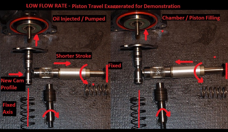
High flow rate. This is when the servo motor forces the flow rate control shaft downward. This allows the longest travel of the piston, increasing cylinder displacement and increasing the pumps output.
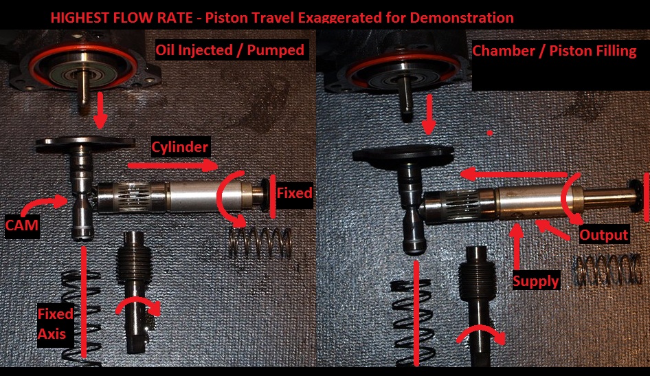
Low flow rate. This is when the servo motor allows the flow rate control shaft to rise. This reduces the travel of the piston, decreasing cylinder displacement and decreasing the pumps output.
Few assumptions:
-even if the servo motor dies, the OMP should still function. However, I would assume the cam profile would remain on the setting when the servo died. Either injecting to much or too little oil depending on RPM.
-To increase ouput, bore out cylinder sleeve, and replace the piston with a matching increased diameter piston. Or, alter the profile of the flow control rate shaft.
Please let me know if any of my statements or assumptions are incorrect so I don't mislead anyone. I just though having pictures might make the OMP's pumping action easier to understand.
===
Working on restoring my FD and wanted to see the condition of my OMP, plus I wanted to see for myself how it worked. The info in the three OMP Declassified threads was awesome, and though I might be able to add.
I am fairly certain I have the following two pictures correctly demonstrating how the OMP uses the rotation from the e-shaft and a cam profile to pump/meter the oil. The operation of the OMP's pumping action is similar to one piston in an axial piston pump.
High flow rate. This is when the servo motor forces the flow rate control shaft downward. This allows the longest travel of the piston, increasing cylinder displacement and increasing the pumps output.

Low flow rate. This is when the servo motor allows the flow rate control shaft to rise. This reduces the travel of the piston, decreasing cylinder displacement and decreasing the pumps output.

Few assumptions:
-even if the servo motor dies, the OMP should still function. However, I would assume the cam profile would remain on the setting when the servo died. Either injecting to much or too little oil depending on RPM.
-To increase ouput, bore out cylinder sleeve, and replace the piston with a matching increased diameter piston. Or, alter the profile of the flow control rate shaft.
Please let me know if any of my statements or assumptions are incorrect so I don't mislead anyone. I just though having pictures might make the OMP's pumping action easier to understand.
07-15-15, 06:29 PM
#29

What's weird is that N326-14-633 comes up as the injector plug itself in the housings: 84-95 13B Rx7 Oil Metering Jet In Rotor Housing...
Perhaps the small rubber grommets are incorrect and I need the "newer" plugs that sit under the injectors?
On a side note the bottom bolt is also now too long thus will need to be replaced with a shorter 10mm bolt.
07-16-15, 01:42 AM
#30
Rotary Freak

Have the grommets been repackaged? Too lazy to look up the part number again to verify, but this is from back when....https://www.rx7club.com/3rd-generati...estion-660786/
The grommets sit under the injector. The oil jet itself, I'm surprised they'd even offer them and can't recall seeing them as a separate item to the housings - late ones at least.
Can't understand the bit about the bolt.
The grommets sit under the injector. The oil jet itself, I'm surprised they'd even offer them and can't recall seeing them as a separate item to the housings - late ones at least.
Can't understand the bit about the bolt.
07-21-15, 01:56 PM
#31
Have the grommets been repackaged? Too lazy to look up the part number again to verify, but this is from back when....https://www.rx7club.com/3rd-generati...estion-660786/
The grommets sit under the injector. The oil jet itself, I'm surprised they'd even offer them and can't recall seeing them as a separate item to the housings - late ones at least.
Can't understand the bit about the bolt.
The grommets sit under the injector. The oil jet itself, I'm surprised they'd even offer them and can't recall seeing them as a separate item to the housings - late ones at least.
Can't understand the bit about the bolt.
07-21-15, 05:59 PM
#32
Rotary Freak
Probably depend if the jet size changed - a set of .1mm increment drills probably required to test that on old and new housings. Here's a couple of pics I'd forgotten I'd taken from years back comparing them...
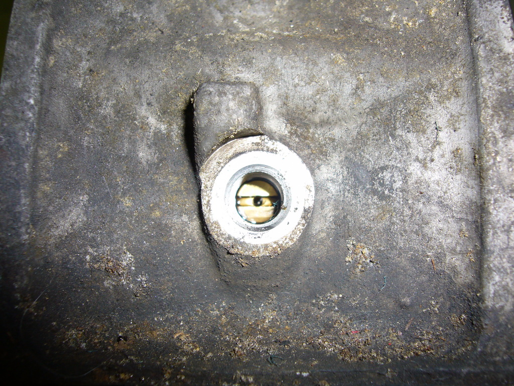
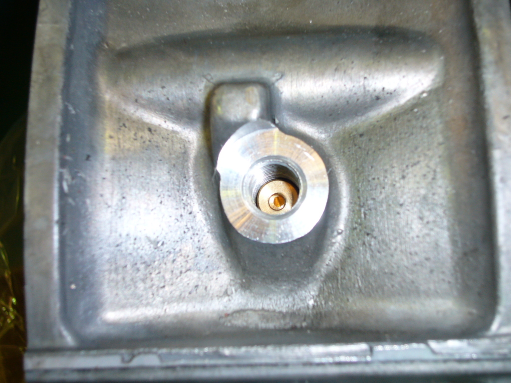
doesn't seem to be a huge difference to the eye at least!


doesn't seem to be a huge difference to the eye at least!
07-21-15, 06:25 PM
#33
Thank you for the pictures, they say 1000 words!
I can't see a point of using the grommets on the older jets when there is a ridge all the way across. They will not seal anything like the newer jets. At this point I am debating just using the old larger injectors with the newer mikuni pump for more oil to flow into the housings.
I can't see a point of using the grommets on the older jets when there is a ridge all the way across. They will not seal anything like the newer jets. At this point I am debating just using the old larger injectors with the newer mikuni pump for more oil to flow into the housings.
07-22-15, 05:10 AM
#34
Rotary Freak
No worries.
Going by the failure rate of oil injectors, I'm surprised there's any good ones left in the larger size. New type is all that has been available here for a very long time.
Going by the failure rate of oil injectors, I'm surprised there's any good ones left in the larger size. New type is all that has been available here for a very long time.
04-20-17, 11:46 AM
#35
Dropping this here, if anyone has any intel on it.
I've been running the Mikuni pump, with a PFC and the newer style injectors with 20/50 oil for a while, and now am suddenly having issues with blowing injectors. Like it blew one on the dyno, and then blew two brand new ones after a day on track. In addition to the more oil that the Mikuni pumps already, the settings in the PFC are pumped up a bit as carryover from previous tune. This is on a new motor.
The theory is, it's pumping so much oil it's overwhelming the check valve (though not sure why it didn't happen before). Going to try the OE/93 style injectors (bigger holes), but wondering if anyone else has had experience with this.
04-20-17, 01:03 PM
#36
I'm under the impression that brand new you can only get the newer style injectors, so I guess you would have to use a set of used older style ones.
So when this happened to you how did you tell that you blew an oil injector? Did you knew right away or later on?
So when this happened to you how did you tell that you blew an oil injector? Did you knew right away or later on?
02-12-18, 01:46 AM
#40
" There is a glitch in using the Mikuni in the 93 - 99 FD's; that is the position sensor will output different voltages from what the PCM is looking for. The Denso position sensor is 500-1800 Ohms and the Mikuni is 500-3400 Ohms. "
How does this work out for modern stand alone ECU's? Is there an option to input the sensor data so the ecu knows full open or closed?
How does this work out for modern stand alone ECU's? Is there an option to input the sensor data so the ecu knows full open or closed?
02-13-18, 10:55 AM
#42
Has anyone ever removed the little brass oil jet from the rotor housing (especially while it's still in the car?)
It looks like it has a flathead screwdriver head, and would just thread out, but I have a replacement set sitting in a baggie, and there are no threads on it at all. How would one even get ahold of the thing to pull it out?
It looks like it has a flathead screwdriver head, and would just thread out, but I have a replacement set sitting in a baggie, and there are no threads on it at all. How would one even get ahold of the thing to pull it out?
02-13-18, 10:59 AM
#43
Has anyone ever removed the little brass oil jet from the rotor housing (especially while it's still in the car?)
It looks like it has a flathead screwdriver head, and would just thread out, but I have a replacement set sitting in a baggie, and there are no threads on it at all. How would one even get ahold of the thing to pull it out?
It looks like it has a flathead screwdriver head, and would just thread out, but I have a replacement set sitting in a baggie, and there are no threads on it at all. How would one even get ahold of the thing to pull it out?
02-13-18, 12:13 PM
#44
Come to think of it, I don't know if my current ones have the slot or not. I can see the o-ring in there, but I want to order a couple new ones before I attempt to pull them out, because it looks like they'd be easy to lose/damage.
I'd like to replace the jets just to eliminate clogging as a cause for blown check valve/nozzles.
I'd like to replace the jets just to eliminate clogging as a cause for blown check valve/nozzles.
02-14-18, 01:43 AM
#45
So...(and I'm making up #s here)
• if the Mikuni is registering 3400 ohms, say that equates to a flow of .05
• if the Mikuni is registering 1800 ohms, say that equates to a flow of .08
On an older gen FD, the lowest flow rate the Mikuni will provide is .08
Someone more certain in their knowledge than me is welcome to eviscerate my explanation.
 02-14-18, 03:00 AM
#46
Dropping this here, if anyone has any intel on it.
I've been running the Mikuni pump, with a PFC and the newer style injectors with 20/50 oil for a while, and now am suddenly having issues with blowing injectors. Like it blew one on the dyno, and then blew two brand new ones after a day on track. In addition to the more oil that the Mikuni pumps already, the settings in the PFC are pumped up a bit as carryover from previous tune. This is on a new motor.
The theory is, it's pumping so much oil it's overwhelming the check valve (though not sure why it didn't happen before). Going to try the OE/93 style injectors (bigger holes), but wondering if anyone else has had experience with this.
I've been running the Mikuni pump, with a PFC and the newer style injectors with 20/50 oil for a while, and now am suddenly having issues with blowing injectors. Like it blew one on the dyno, and then blew two brand new ones after a day on track. In addition to the more oil that the Mikuni pumps already, the settings in the PFC are pumped up a bit as carryover from previous tune. This is on a new motor.
The theory is, it's pumping so much oil it's overwhelming the check valve (though not sure why it didn't happen before). Going to try the OE/93 style injectors (bigger holes), but wondering if anyone else has had experience with this.
One component I always come back to when I consider the OMP system, is the line/s routing from the injector nozzle to the pre-compressor portion of intake in the factory setup. The general argument seems to be that this is/was only done to provide a filtered air source to the OMP injection nozzle so that when there is negative pressure in the engine, filtered air is pulled through the nozzle instead of all the available oil in the OMP lines.
Ok, yes, a filtered air source is important and maybe that really is the only reason. But if so, why are there so many stories of people (such as yourself) blowing check valves so easily/frequently. It may be true, but it's hard to swallow that the Mazda check valves in the nozzles are simply that shitty. A lot of time and money went into the design of the system and it's components. And a lot of stock(ish) cars racked up a lot of miles on them(admittedly there is no immediate indicator if a check valve has gone bad in a factory setup). I'm also pretty sure race teams retained the OMP.
My point (which is more of a question) is this - is there truly no benefit to having a vacuum source attached to the nozzle? Is it not in some way beneficial for the whole thing to be a connected system(as opposed to having a piece vent to atmosphere)? Or beneficial for the check valve to be held closed via vacuum(pull from the intake side) before being slammed shut(hyperbole) by positive engine pressure(push from the engine side) after getting into boost?
I could be grasping at straws. But as mentioned, it's tough to swallow that the nozzle and check valve are simply junk.. so I keep trying to learn/think of something else.
02-14-18, 10:07 AM
#47
I'm actually wondering, though, how much this is really a "single turbo" problem, or just a problem masked by the way it's plumbed in a typical TT system. If I recall, the lines from the nozzles just go to the primary turbo inlet, so there's no vacuum or pressure being applied to the nozzles, and if they were to fail and puke oil, it just get's ingested or puked into the intake so you don't really notice.
I only noticed because I had a dedicated filter to the lines. After it failed, I plumbed the lines to a nipple on the oil filler neck, and then you don't notice anything. It's also worth noting, this doesn't happen on the street. It happens after prolonged boost, like on the track or on the dyno.
I only noticed because I had a dedicated filter to the lines. After it failed, I plumbed the lines to a nipple on the oil filler neck, and then you don't notice anything. It's also worth noting, this doesn't happen on the street. It happens after prolonged boost, like on the track or on the dyno.
02-14-18, 12:53 PM
#48
RX-7 Bad Ass
iTrader: (55)
One thing I wonder about is the whole relationship with the OMP nozzles and boost/vacuum. Non-turbo FC's have the same OMP system as turbo cars and I think the FD has the basic same design.
Big problem with the OMP system is it's not obvious how it works, there's just a lot of guessing and "seems like it works this way" involved. It would be nice to find a way to scientifically test how the system works and what external factors like high boost or changing the vacuum line to the injector will actually do to the system.
Dale
02-14-18, 01:23 PM
#49
Dale, can you confirm my recollection of where the lines from the nozzles are plumbed to on a stock car? If I understand it, there's no vacuum applied to them, they pull vacuum by way of the motor, and are supposed to block boost being expelled. I do know that when they blow, they affect idle, just like adjusting the idle bleed screw.
I'd be surprised though, if they were being blown purely by "high boost" since I only run 13 psi at the track, and I don't understand how 13 psi from TTs is any different than 13 psi from a single turbo.
I'd be surprised though, if they were being blown purely by "high boost" since I only run 13 psi at the track, and I don't understand how 13 psi from TTs is any different than 13 psi from a single turbo.
02-14-18, 11:19 PM
#50
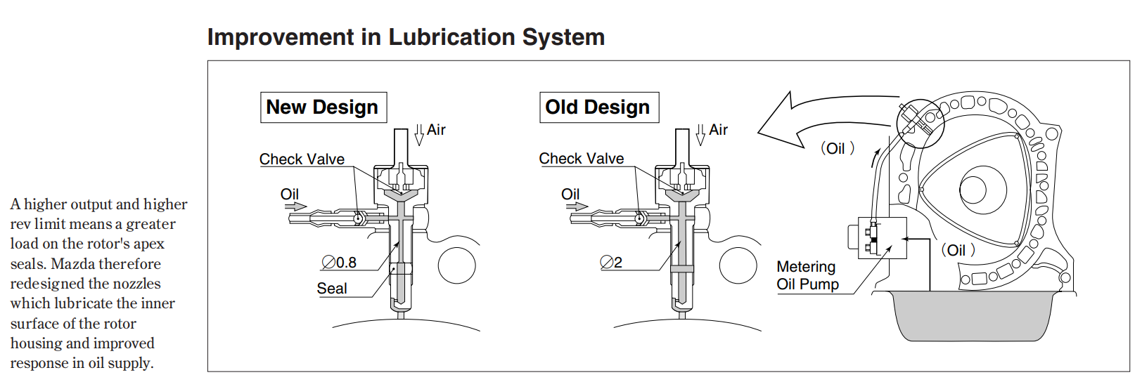
I've looked around for a cross sectional image of injector nozzle because I realized I don't actually know what type of check valve is in there or have any idea what it looks like inside. I've never found any specific literature on this but I did find this image.

This is from a 1999 Mazda press report, it seems to show that the only difference in the nozzle design is the inner diameter and the addition of the seal. Check valve and design appear to be the same (assuming the drawing is accurately representing that part).
Does anyone recognize the type of check valve depicted?