
Non-Sequential Electronic BC Install Help


Non-Sequential Electronic BC Install Help
Hey everyone! need a little help with matching up my EBC to my car.
I have a greddy profec b spec 2 and wanting to wire her up since im overboosting like crazy due to my non-sequential setup. I have it all wired up except for the Solenoid portion portion.
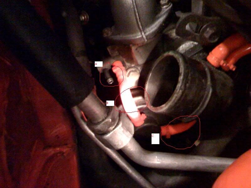
The picture labels A, B & C for the three places im not sure where to connect the COM solenoid or the NO port too.
I was thinking i could connect the COM to part A since its open anyways, and then just T off Part B and connect that to the NO port.
Thanks! here is the picture!
I have a greddy profec b spec 2 and wanting to wire her up since im overboosting like crazy due to my non-sequential setup. I have it all wired up except for the Solenoid portion portion.
The picture labels A, B & C for the three places im not sure where to connect the COM solenoid or the NO port too.
I was thinking i could connect the COM to part A since its open anyways, and then just T off Part B and connect that to the NO port.
Thanks! here is the picture!
i did.. most i got is.. plug the com into the wastegame, and the no into the wastegate..
I figured it would be easy to say "plug com into a, plug no into b" but i guess it isnt.
ill try searching again.
I figured it would be easy to say "plug com into a, plug no into b" but i guess it isnt.
ill try searching again.


Break the boost control system down into its components and it all makes sense.
Hook A into COM, C into NO, and cap B. The pressure source enters the solenoid through the "COM" port. The solenoid is in a "normally open" configuration here. Inside the solenoid, air can pass either direction from the COM port to the NO port. The pressurized air flows out from the NO port into the wastegate at point C in your diagram. When the wastegate actuator sees enough pressure it will begin to open. That is how it works with no voltage applied to the solenoid.
The boost controller increases boost by closing the passageway between COM and NO. As less air leaves the solenoid, less air reaches the actuator, so it will build up pressure slower and open later. Inside the solenoid, the passageway is closed when the boost controller cycles the ground signal on and off rapidly (think about flipping a light switch on and off really fast). The more the solenoid is cycled on, the less air passes through, because without completing the circuit the thing is open. Again, a normally open solenoid closes when the electrical circuit completes. It's the same principle as a electrical relay actually.
The factory boost control solenoid works a little differently.
That nipple you capped off vents air out of the actuator in the factory configuration. You can't have a pressure build up if you vent the air out. Would a teapot whistle if you left the lid open? And without that pressure in the actuator, it won't open. Therefore the factory boost control solenoid allows more air to pass away from the actuator as the stock ECU cycles the ground signal on and off. It is thus an "NO" vacuum solenoid, where applying voltage/duty makes air pass from one port of the solenoid to the other. This is different from the EBC solenoid you are hooking up, where applying air/duty makes less air pass through. But on that configuration, there is no vent.
The whole restrictor pill deal was something installed at the factory so that engineers could always predict how much air was entering the actuator. It makes sense on a factory car but not so much on a modded one.
In either design, all you are doing is limiting the amount of pressure the actuator sees, it's just plumbed in a different way.
That diagram is awesome.. i saw it before but kept searching and couldn't find it again... maybe its a sticky..
Im really dumb so i have some questions.. (at work so its hard to read through it all 100% so ill do that to learn it when i get home)
In my picture i have
"Hook A into COM, C into NO, and cap B."
- i dont get this because B has two ends and C shows being capped in the diagram.
According to the diagram Nipple off the Turbo going into COM (other one capped i suppose)
nipple going from the actuator towards the turbo into the NO port.
Cap the other end of the actuator.
Ill go home and see where "C" is going.
A (one of two nipples coming off the turbo)
B (Turbo Nipple and Actuator Nipple)
C (Actuator Nipple)
So i leave A capped since there is only one wastegate.
I Have B-Turbo Nipple go into COM and B-Actuator Nipple going into NO.
Cap off C.
"That nipple you capped off vents air out of the actuator in the factory configuration."
- i dont think i have anything capped off.
sorry to be such a newb but i wanna make sure i get it.. and i think i understand it but i just want to make sure i don't make it go kaboom!
A is a pressure source from the Y pipe correct? I don't have an FD in front of me at the moment, but we'll assume it is. You are hooking the boost controller in-line with the pressure source and capping the other nipple on the wastegate actuator.
it doesn't matter as much as you think. As long as one nipple on the actuator is capped and one is receiving pressure from the solenoid, it will work fine. Then you just have to cap off anything that could leak. It's just like wiring up a 4-pin relay. 87 and 30 pins can be reversed, and 85/86 pins could either be reversed as power or ground for the coil. You can reverse a bunch of stuff in this case and it will still work. You could reverse which hoses go to "COM" and "NO" even, as long as you don't use the "NC" port.
I'll spare you the technical prattle though, sometimes I ramble on with unnecessary information. Since you want to follow the single turbo vacuum diagram posted, just do it this way:
Cap C
Cap the Y-pipe side of B
Hook A to the "NO" port
Hook B (wastegate side) to the COM port
does that make sense?
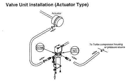
(Spec 2 manual page 9)
Your final result should have the solenoid receiving boost pressure from the car and the wastegate receiving pressure from the solenoid, with anything left over capped.
You REALLY REALLY need to make sure you understand how to tune this boost controller. People blow their motors with this thing. It is not one of the easier ones out there. Download the manual and read pages 16 and 17 thoroughly.
Here is a tuning writeup that originated on an evo forum:
"Before you begin, you should have an idea of what you're aiming for. For EVOs, 19psi (131 kPa) seems to be a safe setting based on what people on the forums have found since it is close to what the stock boost pressure is, yet there is an increase in power due to the Greddy unit keeping the boost close to 19psi while the stock boost tapers off as the RPMs increase. I will henceforth refer to what you're aiming for as "desired boost pressure".
Definitions and things you need to know before you start:
SET This is how you set the boost pressure. Rather than setting it in psi or kPa, the Greddy unit allows you to adjust it as a percentage value, from 0% (greddy unit essentially turned off) to 100% (greddy unit will set the boost as high as it can). This setup demands a certain amount of trial-and-error to properly configure it since you have to make adjustments, then drive under WOT (Wide Open Throttle) and see what the maximum boost pressure achieved was throughout the entire RPM range. SET SHOULD BE SET TO A CONSERVATIVE VALUE WHEN BEGINNING TO TUNE YOUR GREDDY UNIT. 30% SEEMS TO BE A CONSERVATIVE SETTING BASED ON MY TESTING AND BASED ON OTHER REPORTED NUMBERS FROM EVO OWNERS AND TAKING INTO CONSIDERATION THE LINK BETWEEN SET AND GAIN (see GAIN below).
GAIN is defined in the manual as the value to adjust the "boost consistency". You don't really need to know exactly what that means. You should set GAIN to 0 when beginning, and you will then test the car under WOT while paying attention to the boost pressure. If the boost goes up and then falls off at higher RPM, you will want to increase the GAIN by a conservative amount (5% should be relatively conservative to begin with, then when you want to fine-tune it, you can go down to intervals of 1%). When you increase the GAIN value, the corresponding boost that you will go up to will be higher even if you leave the SET value alone. GAIN SHOULD BE SET TO 0 WHEN BEGINNING TO TUNE YOUR GREDDY UNIT.
START BOOST (also known as SET GAIN because that is what is displayed on the unit when adjusting this setting) is the lowest boost that the Greddy unit will begin increasing the boost from under WOT. You want this to be as close to the SET value as possible, since you want to keep as close to your desired boost as possible. However, setting it too close to the SET value will cause the boost to spike. You should set this to a conservative setting when beginning to tune your Greddy unit. Then you can fine-tune it later to get it as close to the SET value as possible without causing the boost to spike. Fortunately, you can set this in psi or kPa, thankfully Greddy didn't decide to let this be adjustable in % like the SET value. START BOOST SHOULD BE SET TO YOUR DESIRED BOOST PRESSURE MINUS 4 PSI (about 28 kPa).
WARNING is the maximum boost that you do not want to exceed. Fortunately, you can also set this in psi or kPa like the START BOOST value. When the boost exceeds the WARNING level, it will kick in the LIMITER, which decreases the boost a certain amount that you can set. WARNING SHOULD BE SET TO YOUR DESIRED BOOST PRESSURE PLUS 1 PSI (about 7 kPa).
LIMITER is the boost percentage that the Greddy unit will lower to when the WARNING boost pressure is hit. LIMITER SHOULD BE SET TO YOUR SET VALUE MINUS 4%.
PEAK is the peak boost value that the unit has seen since the last time it was cleared. To clear it, go to the peak boost display, and hold down the set **** until the unit beeps and "---" is displayed. IT IS A GOOD IDEA TO CLEAR THIS BEFORE YOU BEGIN JUST IN CASE YOUR UNIT HAS A HIGH BOOST ALREADY RECORDED.
LAST BOOST shows you the last boost that was recorded every time the accelerator is released for 3 seconds. TURN LAST BOOST ON BECAUSE IT IS A GOOD DIAGNOSTIC TOOL WHEN TUNING YOUR UNIT.
Keep in mind that when displaying in kPa, it does not show it technically in kPa, but rather misleadingly in bars, which Greddy inconveniently tries to justify by sticking x100 kPa next to the display. Therefore, 100 kPa will be displayed as 1.00 x100 kPa. Psi will also unfortunately be displayed in psi x10 so that 19 psi will show as 190, adding to the confusion.
Another very important thing to keep in mind is that when you first power on your car or the Greddy unit, WARNING will be set to 14.5 psi (100kPa, or 1 bar) until you interact with the Greddy unit by pressing any button. This "feature" is not documented in the manual.
Also keep in mind that atmospheric conditions affect the operation of your boost controller. When it is hot, you will get different results than when it is cold. One possible way of solving this issue is tuning your Greddy unit under the "Lo" mode for when it is relatively cold, and under the "High" mode for when it is relatively hot. Unfortunately, two modes are hardly enough for somebody that needs to account for very different summer and winter climates, and also for more aggressive settings for when increased performance is desired.
The maximum boost that you will see is also not consistent throughout the gears, which adds even more to the confusion. Unfortunately, if you've already increased your start boost to the maximum setting that doesn't give you surging, then there seems to be no way to get around this variance in boost pressure from low to high gears. I don't know if this is a limitation of the greddy unit specifically, or if it's something inherent to electronic boost controllers in general. The only two things that you can do to compensate is the following:
1. Set it to the "safest" of the settings that does not trip your limiter. To do this, tune the unit to your desired boost pressure in fifth gear.
2. Tune the "Lo" and "Hi" settings corresponding to having the boost maximized during the low gears and during the high gears. This would require you to manually hit the button to switch to the "Hi" setting when you shift to third gear or whatever you started tuning your "Hi" setting at. This is why Greddy makes the wireless remote switch that straps to your steering wheel to switch between "Hi" and "Lo" settings.
The following steps should be taken in exactly this order, taking into consideration all of the previous information:
1. Change boost pressure units to psi if so desired (see manual).
2. Set WARNING to your desired boost pressure plus 1 psi (about 7 kPa) (see above).
3. Set START BOOST (SET GAIN) to your desired boost pressure minus 4 psi (about 28 kPa)(see above).
4. Clear PEAK boost value (see above).
5. Set LAST BOOST to ON (see above).
6. Set GAIN to 0 (see above).
7. Set SET to 30% (see above).
8. Set LIMITER to SET minus 4% (26% if you followed #7).
9. Test for boost falloff at high rpm. You should probably do this in a wide open area with no other cars nearby and preferably no cops. It is also good to have somebody in the car with you that can watch the gauge while you concentrate on not wrecking your car. If there is no boost falloff, then go to #10. If there is boost falloff, then increase the GAIN by 5% and test again. Keep in mind that when you increase the GAIN value, the corresponding boost that you will go up to will be higher even if you leave the SET value alone. Repeat until the boost pressure does not decrease, or until you feel surging. If you feel surging and the boost pressure still decreases (not sure if this is possible) then decrease to the last level that you did not feel surging at.
10. Increase SET by 2% and adjust LIMITER accordingly, then test again. Keep increasing by 2% until desired boost level is obtained.
11. Increase START BOOST (SET GAIN) by 1 increment and test until surging is felt or the WARNING level is hit and the display turns red, then decrease to the previous setting.
Once you have followed these steps, you will have roughly tuned your unit. To fine-tune it, repeat steps 9 and 10 except this time only increase or decrease by 1 increment."
"Hook A into COM, C into NO, and cap B."
- i dont get this because B has two ends and C shows being capped in the diagram.
- i dont get this because B has two ends and C shows being capped in the diagram.
I'll spare you the technical prattle though, sometimes I ramble on with unnecessary information. Since you want to follow the single turbo vacuum diagram posted, just do it this way:
Cap C
Cap the Y-pipe side of B
Hook A to the "NO" port
Hook B (wastegate side) to the COM port
does that make sense?
(Spec 2 manual page 9)
Your final result should have the solenoid receiving boost pressure from the car and the wastegate receiving pressure from the solenoid, with anything left over capped.
You REALLY REALLY need to make sure you understand how to tune this boost controller. People blow their motors with this thing. It is not one of the easier ones out there. Download the manual and read pages 16 and 17 thoroughly.
Here is a tuning writeup that originated on an evo forum:
"Before you begin, you should have an idea of what you're aiming for. For EVOs, 19psi (131 kPa) seems to be a safe setting based on what people on the forums have found since it is close to what the stock boost pressure is, yet there is an increase in power due to the Greddy unit keeping the boost close to 19psi while the stock boost tapers off as the RPMs increase. I will henceforth refer to what you're aiming for as "desired boost pressure".
Definitions and things you need to know before you start:
SET This is how you set the boost pressure. Rather than setting it in psi or kPa, the Greddy unit allows you to adjust it as a percentage value, from 0% (greddy unit essentially turned off) to 100% (greddy unit will set the boost as high as it can). This setup demands a certain amount of trial-and-error to properly configure it since you have to make adjustments, then drive under WOT (Wide Open Throttle) and see what the maximum boost pressure achieved was throughout the entire RPM range. SET SHOULD BE SET TO A CONSERVATIVE VALUE WHEN BEGINNING TO TUNE YOUR GREDDY UNIT. 30% SEEMS TO BE A CONSERVATIVE SETTING BASED ON MY TESTING AND BASED ON OTHER REPORTED NUMBERS FROM EVO OWNERS AND TAKING INTO CONSIDERATION THE LINK BETWEEN SET AND GAIN (see GAIN below).
GAIN is defined in the manual as the value to adjust the "boost consistency". You don't really need to know exactly what that means. You should set GAIN to 0 when beginning, and you will then test the car under WOT while paying attention to the boost pressure. If the boost goes up and then falls off at higher RPM, you will want to increase the GAIN by a conservative amount (5% should be relatively conservative to begin with, then when you want to fine-tune it, you can go down to intervals of 1%). When you increase the GAIN value, the corresponding boost that you will go up to will be higher even if you leave the SET value alone. GAIN SHOULD BE SET TO 0 WHEN BEGINNING TO TUNE YOUR GREDDY UNIT.
START BOOST (also known as SET GAIN because that is what is displayed on the unit when adjusting this setting) is the lowest boost that the Greddy unit will begin increasing the boost from under WOT. You want this to be as close to the SET value as possible, since you want to keep as close to your desired boost as possible. However, setting it too close to the SET value will cause the boost to spike. You should set this to a conservative setting when beginning to tune your Greddy unit. Then you can fine-tune it later to get it as close to the SET value as possible without causing the boost to spike. Fortunately, you can set this in psi or kPa, thankfully Greddy didn't decide to let this be adjustable in % like the SET value. START BOOST SHOULD BE SET TO YOUR DESIRED BOOST PRESSURE MINUS 4 PSI (about 28 kPa).
WARNING is the maximum boost that you do not want to exceed. Fortunately, you can also set this in psi or kPa like the START BOOST value. When the boost exceeds the WARNING level, it will kick in the LIMITER, which decreases the boost a certain amount that you can set. WARNING SHOULD BE SET TO YOUR DESIRED BOOST PRESSURE PLUS 1 PSI (about 7 kPa).
LIMITER is the boost percentage that the Greddy unit will lower to when the WARNING boost pressure is hit. LIMITER SHOULD BE SET TO YOUR SET VALUE MINUS 4%.
PEAK is the peak boost value that the unit has seen since the last time it was cleared. To clear it, go to the peak boost display, and hold down the set **** until the unit beeps and "---" is displayed. IT IS A GOOD IDEA TO CLEAR THIS BEFORE YOU BEGIN JUST IN CASE YOUR UNIT HAS A HIGH BOOST ALREADY RECORDED.
LAST BOOST shows you the last boost that was recorded every time the accelerator is released for 3 seconds. TURN LAST BOOST ON BECAUSE IT IS A GOOD DIAGNOSTIC TOOL WHEN TUNING YOUR UNIT.
Keep in mind that when displaying in kPa, it does not show it technically in kPa, but rather misleadingly in bars, which Greddy inconveniently tries to justify by sticking x100 kPa next to the display. Therefore, 100 kPa will be displayed as 1.00 x100 kPa. Psi will also unfortunately be displayed in psi x10 so that 19 psi will show as 190, adding to the confusion.
Another very important thing to keep in mind is that when you first power on your car or the Greddy unit, WARNING will be set to 14.5 psi (100kPa, or 1 bar) until you interact with the Greddy unit by pressing any button. This "feature" is not documented in the manual.
Also keep in mind that atmospheric conditions affect the operation of your boost controller. When it is hot, you will get different results than when it is cold. One possible way of solving this issue is tuning your Greddy unit under the "Lo" mode for when it is relatively cold, and under the "High" mode for when it is relatively hot. Unfortunately, two modes are hardly enough for somebody that needs to account for very different summer and winter climates, and also for more aggressive settings for when increased performance is desired.
The maximum boost that you will see is also not consistent throughout the gears, which adds even more to the confusion. Unfortunately, if you've already increased your start boost to the maximum setting that doesn't give you surging, then there seems to be no way to get around this variance in boost pressure from low to high gears. I don't know if this is a limitation of the greddy unit specifically, or if it's something inherent to electronic boost controllers in general. The only two things that you can do to compensate is the following:
1. Set it to the "safest" of the settings that does not trip your limiter. To do this, tune the unit to your desired boost pressure in fifth gear.
2. Tune the "Lo" and "Hi" settings corresponding to having the boost maximized during the low gears and during the high gears. This would require you to manually hit the button to switch to the "Hi" setting when you shift to third gear or whatever you started tuning your "Hi" setting at. This is why Greddy makes the wireless remote switch that straps to your steering wheel to switch between "Hi" and "Lo" settings.
The following steps should be taken in exactly this order, taking into consideration all of the previous information:
1. Change boost pressure units to psi if so desired (see manual).
2. Set WARNING to your desired boost pressure plus 1 psi (about 7 kPa) (see above).
3. Set START BOOST (SET GAIN) to your desired boost pressure minus 4 psi (about 28 kPa)(see above).
4. Clear PEAK boost value (see above).
5. Set LAST BOOST to ON (see above).
6. Set GAIN to 0 (see above).
7. Set SET to 30% (see above).
8. Set LIMITER to SET minus 4% (26% if you followed #7).
9. Test for boost falloff at high rpm. You should probably do this in a wide open area with no other cars nearby and preferably no cops. It is also good to have somebody in the car with you that can watch the gauge while you concentrate on not wrecking your car. If there is no boost falloff, then go to #10. If there is boost falloff, then increase the GAIN by 5% and test again. Keep in mind that when you increase the GAIN value, the corresponding boost that you will go up to will be higher even if you leave the SET value alone. Repeat until the boost pressure does not decrease, or until you feel surging. If you feel surging and the boost pressure still decreases (not sure if this is possible) then decrease to the last level that you did not feel surging at.
10. Increase SET by 2% and adjust LIMITER accordingly, then test again. Keep increasing by 2% until desired boost level is obtained.
11. Increase START BOOST (SET GAIN) by 1 increment and test until surging is felt or the WARNING level is hit and the display turns red, then decrease to the previous setting.
Once you have followed these steps, you will have roughly tuned your unit. To fine-tune it, repeat steps 9 and 10 except this time only increase or decrease by 1 increment."
Trending Topics
that was absolutely amazing.
hooked it up last night.
took her out today after making the setting on the EBC for pre-tuning.
made some tweeks and now she is boosting right up to 10 and holding in every gear no problems!
Thanks again for all your help!
I have a boost controller so seeing what the boost is and then verifying it with the peal is nice.
Thanks!
Break the boost control system down into its components and it all makes sense.
Hook A into COM, C into NO, and cap B. The pressure source enters the solenoid through the "COM" port. The solenoid is in a "normally open" configuration here. Inside the solenoid, air can pass either direction from the COM port to the NO port. The pressurized air flows out from the NO port into the wastegate at point C in your diagram. When the wastegate actuator sees enough pressure it will begin to open. That is how it works with no voltage applied to the solenoid.
The boost controller increases boost by closing the passageway between COM and NO. As less air leaves the solenoid, less air reaches the actuator, so it will build up pressure slower and open later. Inside the solenoid, the passageway is closed when the boost controller cycles the ground signal on and off rapidly (think about flipping a light switch on and off really fast). The more the solenoid is cycled on, the less air passes through, because without completing the circuit the thing is open. Again, a normally open solenoid closes when the electrical circuit completes. It's the same principle as a electrical relay actually.
The factory boost control solenoid works a little differently.
That nipple you capped off vents air out of the actuator in the factory configuration. You can't have a pressure build up if you vent the air out. Would a teapot whistle if you left the lid open? And without that pressure in the actuator, it won't open. Therefore the factory boost control solenoid allows more air to pass away from the actuator as the stock ECU cycles the ground signal on and off. It is thus an "NO" vacuum solenoid, where applying voltage/duty makes air pass from one port of the solenoid to the other. This is different from the EBC solenoid you are hooking up, where applying air/duty makes less air pass through. But on that configuration, there is no vent.
The whole restrictor pill deal was something installed at the factory so that engineers could always predict how much air was entering the actuator. It makes sense on a factory car but not so much on a modded one.
In either design, all you are doing is limiting the amount of pressure the actuator sees, it's just plumbed in a different way.
Are you using the stock wastegate solenoid or a 3 port solenoid? You really should just get a 3 port solenoid as the factory solenoid + restricter pill really doesn't work too well on a modified setup.
http://www.frightprops.com/pneumatic...-orifices.html
12v DC version. $26.50
then use this connector to plug into the factory wastegate solenoid plug http://www.bmotorsports.com/shop/pro...oducts_id/1674 or you can hardwire it if you don't care about having a plug

You will have to change one setting in the PFC with a Datalogit for this to work right, otherwise you might have a boost spike. Turbo transition should be set to 1800rpm for low and 2000rpm for high. Sequential turbo control should be ON. I know that keeping sequential turbo control on doesn't sound right, but that's what you need to do. Boost is adjusted with the "boost" and duty settings in the Commander or the Datalogit, just as it was with sequential twins. I set the Primary and Secondary values to be the same.
http://www.frightprops.com/pneumatic...-orifices.html
12v DC version. $26.50
then use this connector to plug into the factory wastegate solenoid plug http://www.bmotorsports.com/shop/pro...oducts_id/1674 or you can hardwire it if you don't care about having a plug
You will have to change one setting in the PFC with a Datalogit for this to work right, otherwise you might have a boost spike. Turbo transition should be set to 1800rpm for low and 2000rpm for high. Sequential turbo control should be ON. I know that keeping sequential turbo control on doesn't sound right, but that's what you need to do. Boost is adjusted with the "boost" and duty settings in the Commander or the Datalogit, just as it was with sequential twins. I set the Primary and Secondary values to be the same.
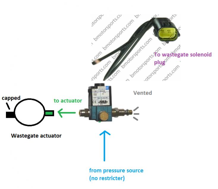
Unlike what you see in the picture, you will have to install a barbed fitting in the middle port. In an internal wastegate configuration, air goes in through the middle port and out the left port (same as on a lot of other 3 port boost control solenoids).
out of all the NS setups i have never seen this way...^^^. I do not have a datalogit yet, so in the mean time is there a way to just hook it up so that way i can get the car to run?
The plumbing is exactly the same as a Profec B spec II. Exactly.
It's a 3 port solenoid (same manufacturer as the AEM solenoid) just like the Denso solenoid used by Greddy and Apex'i. The solenoid is driven by the PFC instead of a separate box, that's all. There's nothing unusual about it; 3 port solenoid conversions are done on Evos and STi's all the time. Grimmspeed, Perrin, and other brands sell similar 3 port solenoids. This is like a $30 setup as long as you have access to a Datalogit to change that one setting. If you don't change that turbo transition setting in the PFC you may have overboosting problems.
If you just want the car to run you can eliminate the boost controller completely. Have a hose go from a pressure source (no restricter pill in-line) to one port on the wastegate actuator. Then cap the other port. You are just eliminating the solenoid. Or use a cheapie manual boost controller.

Thread
Thread Starter
Forum
Replies
Last Post
Jeff20B
1st Generation Specific (1979-1985)
73
Sep 16, 2018 07:16 PM
[For Sale] Scratch & Dent, Used, and Open-Box Sale!
SakeBomb Garage
Vendor Classifieds
5
Aug 9, 2018 05:54 PM