
my Power FC, LC-1, datalogit wiring diagram


my Power FC, LC-1, datalogit wiring diagram
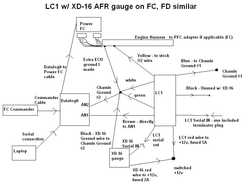
This is a wiring diagram for a Power FC, LC-1 wideband with the XD-16 AFR gauge, a datalogit, and a commander. It is for the 7 wire LC-1 that most people have. The early production LC-1 had only 6 wires. This is how I have everything currently wired up to my car, 88 Turbo II using Banzai Racing Power FC adapter harness.
I created this diagram initially for myself to make sense of all the threads in the Power FC forum about how to put all this together. So here is my contribution. Note that this should work similarly for an FD, but there might be some slight differences that I am not aware of. You do not need that extra ECU ground I suppose but it is a very common to make one on a 2nd gen.
Index of wires:
LC1 wires:
red +12v, fused 5A
blue heater ground
white system ground
green analog ground
yellow analog output #1, usually used to simulate a narrowband
brown analog output #2, used for a 0-5v signal like the datalogit expects
black calibration wire. this is only needed if you do not have the XD-16 gauge
Serial OUT connects to XD-16 or a laptop
Serial IN usually not used. you MUST use the included terminator plug for this
the blue heater ground runs to a separate chassis ground source in order to prevent electrical noise.
XD-16 AFR gauge
red +12v, fused 2A
black ground
Serial IN connects to LC-1 to get the AFR data
The XD-16 has a button on it to calibrate the LC-1, which eliminates the need for the LC-1's black wire.
Datalogit
AN1 0-5v input
AN2 in this configuration, it will receive the ground signal.
PFC cable connects to Power FC
Serial cable connects to laptop
Engine harness/ Power FC
ECU ground many run an extra wire to the chassis from the stock ground wires
O2 wire connect the stock O2 sensor wire to the yellow wire on the LC-1
Both of these connections are optional. Most people turn off O2 feedback.
Also note that you must use the Delta AN1-AN2 feature under the auxilary input setup for the datalogit to understand the signal correctly. You also must make sure that the datalogit, the LC-1, and the XD-16 all have the voltage scaled to the AFR range you are using. See the respective instruction manuals for how to do this.
Also see this thread for more info: https://www.rx7club.com/showthread.p...&highlight=LC1
and here is Innovate's writeup for doing all this, which unfortunately does not have a diagram:
http://www.innovatemotorsports.com/r...1_Tutorial.pdf


Thread
Thread Starter
Forum
Replies
Last Post
streetlegal?
New Member RX-7 Technical
13
Mar 17, 2022 02:46 PM
fastsaab
New Member RX-7 Technical
5
Aug 19, 2015 11:42 AM