making Carbon Fiber brake duct backing plates - pics
 10-07-04, 09:08 PM
#1
making Carbon Fiber brake duct backing plates - pics
I am making some carbon fiber brake duct baking plates and here are some pics and info so far:
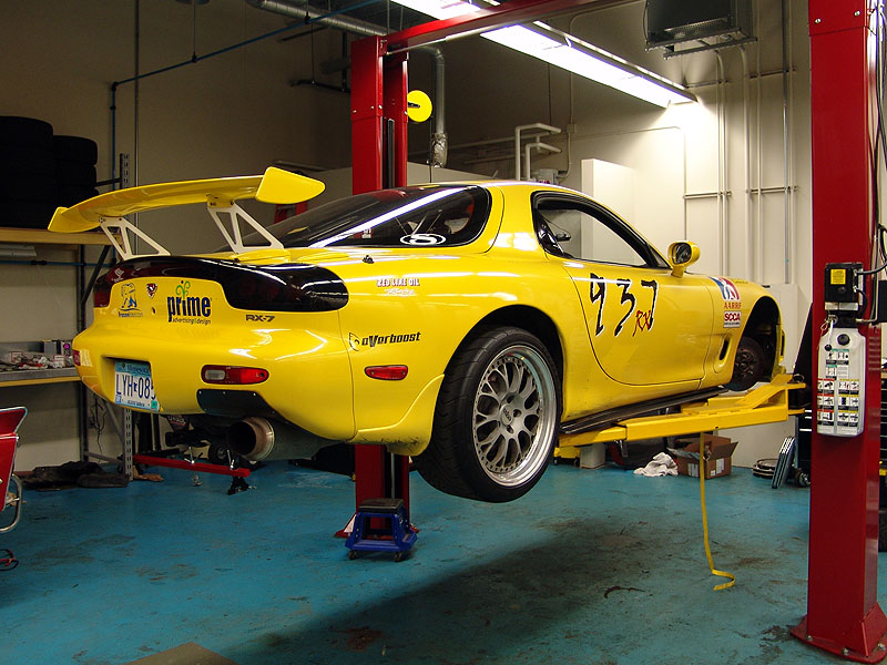
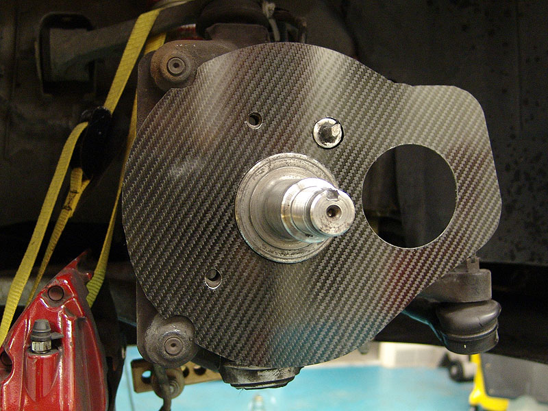
Here is the car on the lift, getting ready to be test fitted with the backing plates:
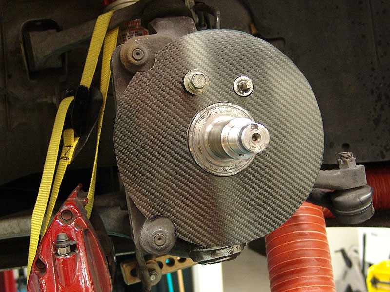
Here is my first design being test fitted:
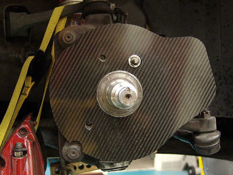
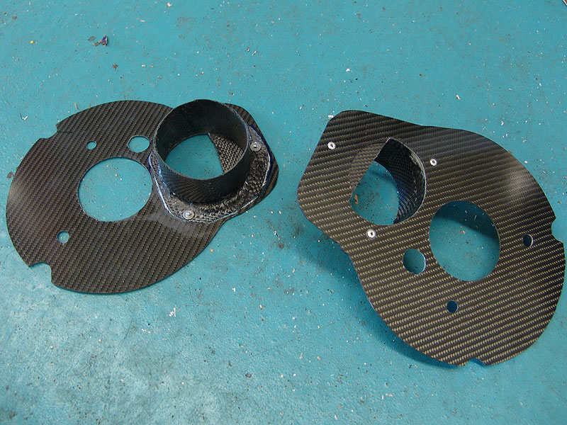
I realized I needed more material where the 3" hose flange was going to attach so I re-designed the shape with that in mind, here is what the final shape looked like:
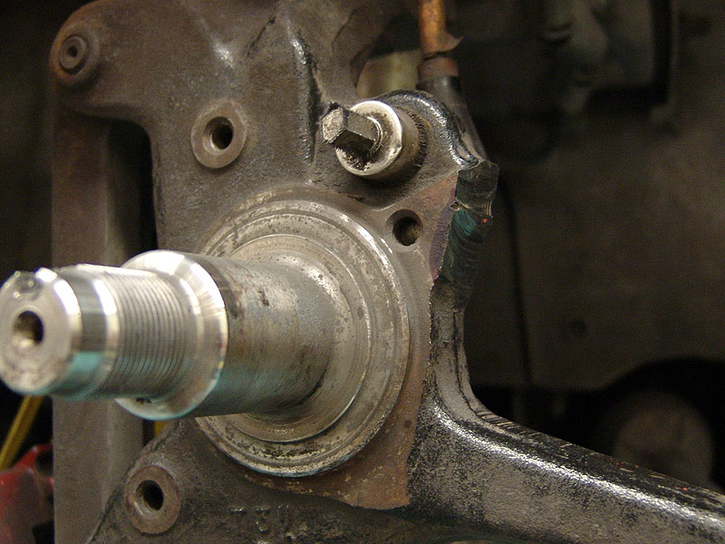
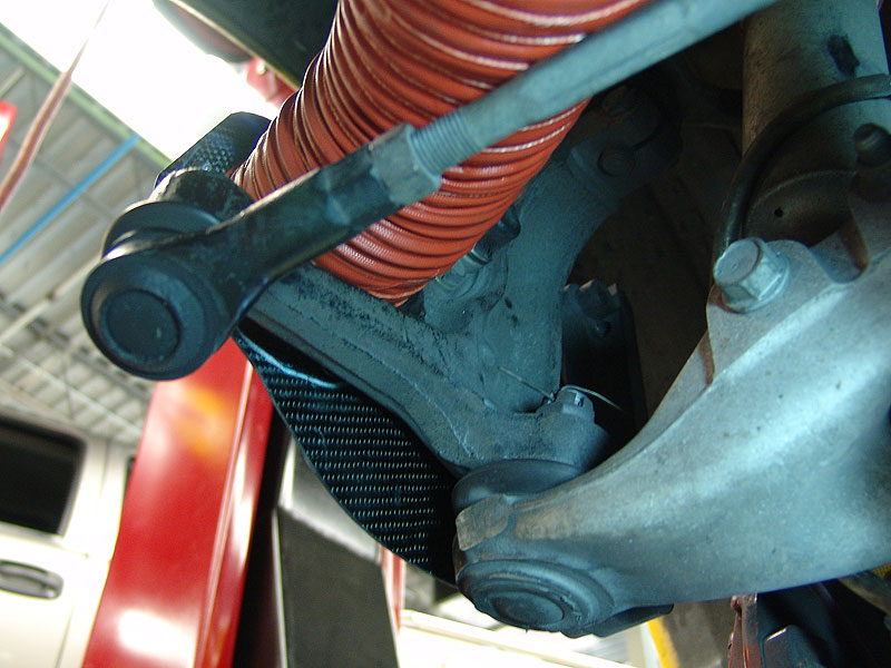
There is a small flange that has a hole for a stock backing plate duct bolt, this is no longer needed and in the way for optimal placement of the hose flang, so I cut it off, here you can see where that was:
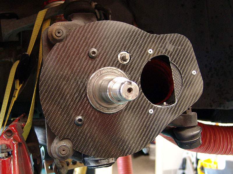
The final shape with the vent hole cut into it, ready to have the hose flange attached:
I'll post more pics/info as I complete more steps. I have the templates I made for the design and will probably offer these for sale at some point if there is interest.
Here is the car on the lift, getting ready to be test fitted with the backing plates:
Here is my first design being test fitted:
I realized I needed more material where the 3" hose flange was going to attach so I re-designed the shape with that in mind, here is what the final shape looked like:
There is a small flange that has a hole for a stock backing plate duct bolt, this is no longer needed and in the way for optimal placement of the hose flang, so I cut it off, here you can see where that was:
The final shape with the vent hole cut into it, ready to have the hose flange attached:
I'll post more pics/info as I complete more steps. I have the templates I made for the design and will probably offer these for sale at some point if there is interest.
Last edited by damian; 10-07-04 at 09:11 PM.

 10-07-04, 09:42 PM
#6
Eats, Sleeps, Dreams Rotary
iTrader: (4)
Join Date: Apr 2003
Location: Denver, NC
Posts: 3,531
Likes: 0
Received 0 Likes
on
0 Posts
Funny how when You do this Damian everyone loves it! But when Skunks and I designed ours last year we just got shiat!! Wish I was as popular as you
Very nice stuff. What size hole nd tubing are you using? D'oH!! Just saw the 3 inch hose... Where did you get it from?
It looks like you have the air directed at the rotor face.. is that correct? Ours has the air directed into the vanes on the inside so the cooling air is forced to is desired place.
I am intrested to see if you have any cracking issues once on the track. As that is what we were told by just about everyone.Regardless of the fact that 75% of the air is getting into the vanes and hardly any hitting the face directly.
Wish I was as popular as youVery nice stuff. What size hole nd tubing are you using? D'oH!! Just saw the 3 inch hose... Where did you get it from?
It looks like you have the air directed at the rotor face.. is that correct? Ours has the air directed into the vanes on the inside so the cooling air is forced to is desired place.
I am intrested to see if you have any cracking issues once on the track. As that is what we were told by just about everyone.Regardless of the fact that 75% of the air is getting into the vanes and hardly any hitting the face directly.
Last edited by BigIslandSevens; 10-07-04 at 10:00 PM.
Trending Topics
10-08-04, 12:28 AM
#8
Originally Posted by Klar
Aren't you running out of room with those tires in the front?
10-08-04, 12:38 AM
#9
dood, i didnt even know you did!!! let me go search the threads again.
>>Just saw the 3 inch hose... Where did you get it from?
got the hose from http://www.racerpartswholesale.com/duct.htm (bottom one)
>>It looks like you have the air directed at the rotor face.. is that correct?
nope, the air is directed in the hole, however cuz the 3" is soooo dam big a small portion of it does hit the face of the rotor, remember I have 'big reds' so the rotor 'hole' is huge. it does direct the air into the veins, and this is perfect for the porsche directional vein rotors that 'suck' air out of the center.
>>I am intrested to see if you have any cracking issues once on the track.
are you talking about crackin rotors? or?
10-08-04, 12:41 AM
#10
Originally Posted by jimlab
Damian, do you work? We know you don't have a "significant other" to tie up your time and keep you from going to the track. 
hahah, i work all the time, how do you think i pay for all this ridiculousness!!!
i am just veeeeerrrrry good at time management ;-)
by the way, look who is talking!!!!
10-08-04, 03:15 AM
#12
Eats, Sleeps, Dreams Rotary
iTrader: (4)
Join Date: Apr 2003
Location: Denver, NC
Posts: 3,531
Likes: 0
Received 0 Likes
on
0 Posts
Yeah we made some.( Let me clarify... Skunks made them i supplied the miold )They look a bit different. I think Skunks labeled them "cling-on death stars"
I was just playin around with the forum public with the bandwagon type comment
I forgot about your mongo rotors. They will definetly get the air to the hole. Makes sense with the bigger CF surface area than ours.
The link in the race car section that had pics is dead. I'll send you some in the email. I have to go dig them up.
https://www.rx7club.com/showthread.p...er+brake+ducts
Thanks for the link to the hose connection.
And yes i meant the rotors cracking. That is a common side effect of forceing cooler air onto hot surfaces. Warpage and/or cracking. More so with drilled rotors espeacially. I don't expect much of a problem. But we'll see.
)They look a bit different. I think Skunks labeled them "cling-on death stars" I was just playin around with the forum public with the bandwagon type comment
I forgot about your mongo rotors. They will definetly get the air to the hole. Makes sense with the bigger CF surface area than ours.
The link in the race car section that had pics is dead. I'll send you some in the email. I have to go dig them up.
https://www.rx7club.com/showthread.p...er+brake+ducts
Thanks for the link to the hose connection.
And yes i meant the rotors cracking. That is a common side effect of forceing cooler air onto hot surfaces. Warpage and/or cracking. More so with drilled rotors espeacially. I don't expect much of a problem. But we'll see.
Last edited by BigIslandSevens; 10-08-04 at 03:18 AM.
10-08-04, 07:29 AM
#13
Lives on the Forum
You want to force as much air as you can into the inner diameter (eye) of the rotor so the air will travel through the middle of the rotor along the cooling vanes and to the outer circumference. If you merely bring air to one face of the rotor you only cool one side and that isn't good for rotor longevity or cooling efficiency. Ideally you have a backing plate that seals to the inner eye of the rotor and then dump all the air into that. In that case all air must actually travel through the rotor before it can exit but this is impossible on some cars.
This pic shows such a backing plate that seals to the rotor eye. It does not extend to the face of the rotor

Installed

This pic gives a better view of the same idea installed

Another set of backing plates that seal to the rotor eye. Notice how there is essentially a large "ear" where the hose attaches. The backer is essentially a plenum that dumps into the center of the rotor.

Another idea that allows easy manufacture and attachment of the hose but still forces all air through the eye

If you can't make a plate that seals to the eye you at least want to dump all your cooling air into that area and not onto the rotor face(s). Merely pointing to the faces doesn't cool near as well as the air doesn't travel through the core of the rotor and unless you have two ducts the outer face gets nothing. It's better than nothing but terribly inefficient use of the cooling air.
Ideally you cut your backing plate just shy of the eye diameter of the rotor and add a lip that extends slightly into the interior of the rotor's eye and dump all your air in there; then all cooling air must travel through the internal cooling vanes of the rotor. On the FD I would expect there will not be room to just stuff a 3" hose onto that because of spindle and wheel clearance issues (if you have larger diameter than stock wheels this may not be difficult though). If there isn't room to just add the hose you must create a sheetmetal duct that connects between your backing plate and your hose. The end attaching to the backing plate will be shaped like an oval or crescent and then transition to a round tube at the other end to attach your hose. This is actually quite easily made by rolling sheetmetal into a funnel shape (picture it by using a piece of paper) and forming both ends to the shapes you wish. Pop rivet and seal the metal along the seam and then rigidly attach it to the backing plate for support and to ensure it holds its shape. The hose end doesn't need to be a perfect circle but it should be close so the hose doesn't pull off easily.
Even if you had no backing plate at all it's still best to bring all the air to the inner eye of the rotor rather than just pointing it at the face. Obviously a sealing backing plate offers another huge increase in efficiency though. Air takes the path of least resistance and just pointing it to the eye does not actually force it through the rotor even though the internal vanes may act like a pump. Much of the air will just blow past the spindle and never travel through the rotor if it's not forced to stay inside the rotor.
My apologies if I'm making a bunch of suppositions about this project without seeing it firsthand.
This pic shows such a backing plate that seals to the rotor eye. It does not extend to the face of the rotor
Installed
This pic gives a better view of the same idea installed
Another set of backing plates that seal to the rotor eye. Notice how there is essentially a large "ear" where the hose attaches. The backer is essentially a plenum that dumps into the center of the rotor.
Another idea that allows easy manufacture and attachment of the hose but still forces all air through the eye
If you can't make a plate that seals to the eye you at least want to dump all your cooling air into that area and not onto the rotor face(s). Merely pointing to the faces doesn't cool near as well as the air doesn't travel through the core of the rotor and unless you have two ducts the outer face gets nothing. It's better than nothing but terribly inefficient use of the cooling air.
Ideally you cut your backing plate just shy of the eye diameter of the rotor and add a lip that extends slightly into the interior of the rotor's eye and dump all your air in there; then all cooling air must travel through the internal cooling vanes of the rotor. On the FD I would expect there will not be room to just stuff a 3" hose onto that because of spindle and wheel clearance issues (if you have larger diameter than stock wheels this may not be difficult though). If there isn't room to just add the hose you must create a sheetmetal duct that connects between your backing plate and your hose. The end attaching to the backing plate will be shaped like an oval or crescent and then transition to a round tube at the other end to attach your hose. This is actually quite easily made by rolling sheetmetal into a funnel shape (picture it by using a piece of paper) and forming both ends to the shapes you wish. Pop rivet and seal the metal along the seam and then rigidly attach it to the backing plate for support and to ensure it holds its shape. The hose end doesn't need to be a perfect circle but it should be close so the hose doesn't pull off easily.
Even if you had no backing plate at all it's still best to bring all the air to the inner eye of the rotor rather than just pointing it at the face. Obviously a sealing backing plate offers another huge increase in efficiency though. Air takes the path of least resistance and just pointing it to the eye does not actually force it through the rotor even though the internal vanes may act like a pump. Much of the air will just blow past the spindle and never travel through the rotor if it's not forced to stay inside the rotor.
My apologies if I'm making a bunch of suppositions about this project without seeing it firsthand.
Last edited by DamonB; 10-08-04 at 08:16 AM.
10-08-04, 08:45 AM
#14
Racing Rotary Since 1983
iTrader: (6)
Damian... nice job however i do agree w DamonB as to the necessity of ducting ALL of the air into the hub/interior of the rotor. i have concerns (rotor warpage) as to blowing air onto the exterior of one side of the rotor. you should have less than a tenth of an inch clearance between the rotor and the duct.
dealing w full steering lock tire/body clearance is a major engineering excercise as i am sure you have already realized. i am happy that my brake setup is such that it doesn't need ducts.
good luck,
howard coleman
dealing w full steering lock tire/body clearance is a major engineering excercise as i am sure you have already realized. i am happy that my brake setup is such that it doesn't need ducts.
good luck,
howard coleman
10-08-04, 10:17 AM
#15
bummer the pics dont work, i cant see what you did
:-(
:-(
Originally Posted by BigIslandSevens
Yeah we made some.( Let me clarify... Skunks made them i supplied the miold)They look a bit different. I think Skunks labeled them "cling-on death stars"
I was just playin around with the forum public with the bandwagon type comment
I forgot about your mongo rotors. They will definetly get the air to the hole. Makes sense with the bigger CF surface area than ours.
The link in the race car section that had pics is dead. I'll send you some in the email. I have to go dig them up.
https://www.rx7club.com/showthread.p...er+brake+ducts
Thanks for the link to the hose connection.
And yes i meant the rotors cracking. That is a common side effect of forceing cooler air onto hot surfaces. Warpage and/or cracking. More so with drilled rotors espeacially. I don't expect much of a problem. But we'll see.
)They look a bit different. I think Skunks labeled them "cling-on death stars" I was just playin around with the forum public with the bandwagon type comment
I forgot about your mongo rotors. They will definetly get the air to the hole. Makes sense with the bigger CF surface area than ours.
The link in the race car section that had pics is dead. I'll send you some in the email. I have to go dig them up.
https://www.rx7club.com/showthread.p...er+brake+ducts
Thanks for the link to the hose connection.
And yes i meant the rotors cracking. That is a common side effect of forceing cooler air onto hot surfaces. Warpage and/or cracking. More so with drilled rotors espeacially. I don't expect much of a problem. But we'll see.
10-08-04, 10:32 AM
#16
thanks for all the great comments guys, I understand all the points, but there is a definet line between what I want for perfection and what I can do limited by fabrication/time/money restrictions :-)
I did plenty of research before i started this and knew all the little things to make them 'perfect', like the lip ont eh backingplate to 'seal' the hole, making sure to get all the air to the center, et, et... then from that I cut things out to accomodate for easy of fabrication, what was possible in the time frame i have to work on it, and cost.
...my game here was not to make the perfect backing plate ever made, rather my goal was just to get some air in there, as some air is better than no air,..... this was with one stedfast rule... that it was mainly be directed in the eye of the rotor, i never had a notion of blowing air on the face of the rotor for obvious reasons.
there is one think i did garner out of all the great feedback, I may tweak the flang inlet that attaches to the backingplate so that it blocks off teh small part that would blow on the edge of the rotor face, similar to blue ones in the pics above.
ill keep the pics and status coming, you guys keep the good feedback coming!!
and howard, get that think running right so we can play at BIR together, I need a 3rd gen racing mentor :-)
Last edited by damian; 10-08-04 at 10:35 AM.
10-08-04, 12:07 PM
#17
Eats, Sleeps, Dreams Rotary
iTrader: (4)
Join Date: Apr 2003
Location: Denver, NC
Posts: 3,531
Likes: 0
Received 0 Likes
on
0 Posts
See what i mean Damian.. The "doubters" are out allready!! And you and I have both stated that the air IS traveling to the EYE of the rotor... NOT the face Then thru the vanes to cool. Yet everyone still feels the need to type out a 10 paragraph explanation of how to do what we already did.
However I relize it is hard to tell from pics But they are designed correctly.
No offense DamonB.. That is great info for the people that don't know. However, Just cause our ducts don't say crooked willow or some other name brand, doesn't mean we didn't design them correctly. Not saying you are saying that, but that is the inference IMO.Just because the CF plate covers the entire rotor face does NOT mean that we are dumping all the air onto the rotor face. If that were the case then the original parst suck! As they do the exact same principle as mine and Damian's.. Just with cheaper materials and less effieciency. They only have a angled piece of tin to direct the air towards the rotor eye. we have direct induction So to speak.
And that little directional flap that the blue ones have is the same theory i am using to make the block -off flap for the rotor face.
As Damian said.. Perfection is not the ultimate goal. Cooler brakes are!! And at a decent $$. Plus the CF fumes are sooo sweet
Then thru the vanes to cool. Yet everyone still feels the need to type out a 10 paragraph explanation of how to do what we already did. However I relize it is hard to tell from pics
But they are designed correctly.No offense DamonB.. That is great info for the people that don't know. However, Just cause our ducts don't say crooked willow or some other name brand, doesn't mean we didn't design them correctly. Not saying you are saying that, but that is the inference IMO.Just because the CF plate covers the entire rotor face does NOT mean that we are dumping all the air onto the rotor face. If that were the case then the original parst suck! As they do the exact same principle as mine and Damian's.. Just with cheaper materials and less effieciency. They only have a angled piece of tin to direct the air towards the rotor eye. we have direct induction So to speak.
And that little directional flap that the blue ones have is the same theory i am using to make the block -off flap for the rotor face.
As Damian said.. Perfection is not the ultimate goal. Cooler brakes are!! And at a decent $$. Plus the CF fumes are sooo sweet
Last edited by BigIslandSevens; 10-08-04 at 12:13 PM.
10-08-04, 01:35 PM
#19
Lives on the Forum
Originally Posted by BigIslandSevens
The "doubters" are out allready!!... Just cause our ducts don't say crooked willow or some other name brand, doesn't mean we didn't design them correctly. Not saying you are saying that, but that is the inference IMO.
If the backing plate does not seal closely with a lip or actually fill the inside of the rotor eye you're merely hoping that all your air goes through the rotor and are inevitably wasting a lot of the cooling air you made the effort to duct from the front of the car to the rotor in the first place. With a flat plate set some distance away from the eye rather than in it much of the air will just spill back out without being forced through the rotor. All you have to do to what is already there is add a lip that sticks out just inside the rotor eye and have the hose enter inside that lip. The lip will essentially allow you to build ram air pressure that forces air through the rotor. Without it air will just blow by except for what the rotor vanes manage to pull in on their own, you can't force more through them as the air will just leak out the backing plate instead.
...and the stock backing plates as far as brake cooling is concerned do completely suck. I don't know why you expect argument on that?
The point of my post (and if I'm allowed I would say Howard's as well) is that if you're going to go to this much trouble you can have a far better solution by just investing a small amount of additional work. IMO it didn't seem like it was realized how fundamental a difference that lip really is.
Last edited by DamonB; 10-08-04 at 01:40 PM.
10-08-04, 01:49 PM
#20
Eats, Sleeps, Dreams Rotary
iTrader: (4)
Join Date: Apr 2003
Location: Denver, NC
Posts: 3,531
Likes: 0
Received 0 Likes
on
0 Posts
I am not expecting arguments...specifically from you. I know you were just explaining the theory to others .. That is why i said "No offense DamonB, That is good info for those that do not know it already"
That's all man. Sorry to offend you. It just gets old explaining the same stuff time after time after time, when I already stated how they are flowing air in. AGAIN, This is not directed towards you. I give you enough credit to at least "read" the words that people post along with pictures.
Again, I expect no arguments on anything and am offering none. Sorry to offend you and get a another 10 paragraph explanation.
Quote"
The point of my post (and if I'm allowed I would say Howard's as well) is that if you're going to go to this much trouble you can have a far better solution by just investing a small amount of additional work. IMO it didn't seem like it was realized how fundamental a difference that lip really is."
And I thought we explanied that we were perfecting or moddifing them to work better. Maybe you missed that part though.
10-08-04, 02:04 PM
#21
hey DamonB, I didnt take ur comments as negative, i knew what you were saying, I just want to point out that I did my design based on my porsche rotors that have directional veins that 'pull' air from the center, to while rotating they create a low pressure area there, so even without a 'lip' it will use a most the air that gets there, it will basically be sucking it in.
>>The point of my post (and if I'm allowed I would say Howard's as well) is that if you're going to go to this much trouble you can have a far better solution by just investing a small amount of additional work.
i think you missed my point about time, I am ALREADY 'investing a small amount of additional work' in doing ANY sort of backing plate and brake ducts, so my point was I didnt have any more time to spend making minor changes like the lip and whatever. see what im sayin.
that dosnt mean that in the winter when I have more time I wont tweak the baking plates to be 'better' that my curent design, but no matter what anyone sais here, gettin ANY air to the rotor hole will help cool the brakes, period..... and that was my intent.
10-09-04, 06:44 PM
#23
Update:
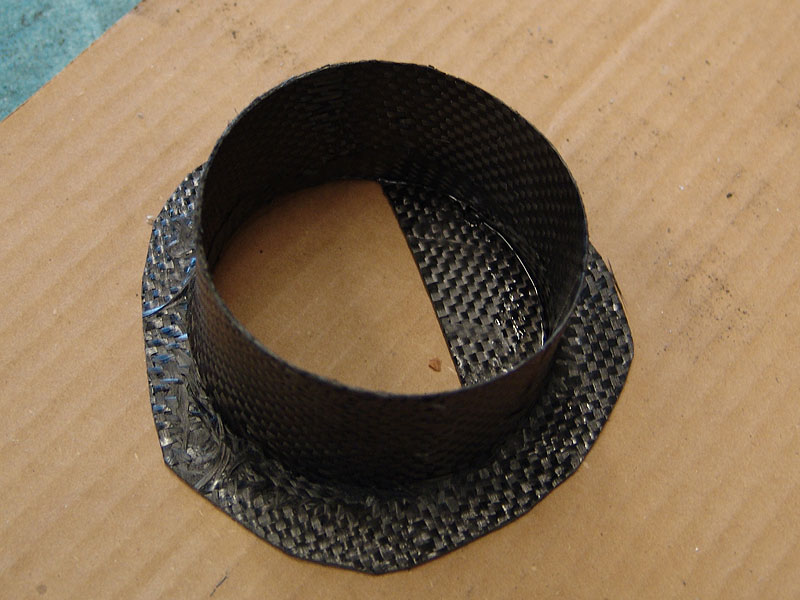
I stopped in the shop and my man Noah from speedlab (http://speedlabmotorsports.com/) had already fabbed a prototype hose flange for my backing plates, I was expecting fiberglass, but to my surprise and delight, he made them out of carbonfiber :-)
At one point I hear him say somthing like 'Damian....check this out', I look over and Noah is standing on the test cf flange, with all his weight. It was an impressive display of material strength, all his weight supported by that tiny flange tube, a mere 2 layers of cf with some expoxy. wow.
We did incorporate one of the ideas that came from the feedback from you guys. We made a blocking flap of cf to make sure there is no air blowing directly on the rotor. The pics will show what I mean.
Here is a shot of the final flange design, notice the blocking flap:
Here is a pic of both backing plates with the hose flanges attached (rivets and epoxy):
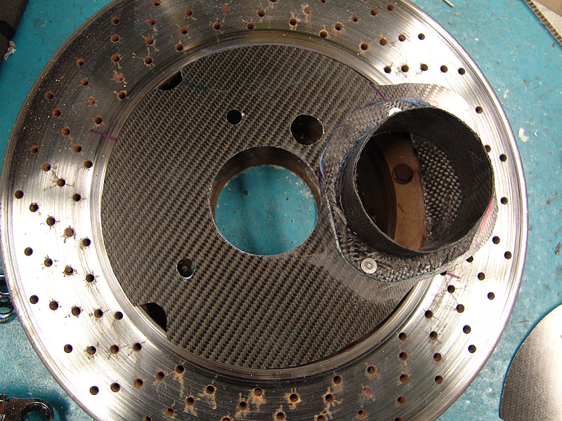
A shot of backingplate sitting on a rotor, notice how none of the rotor is exposed in the air outlet hole:
A pic of it on the car:
A shot from behind the spindle:
I am really pumped how well they came out, I'll have more pics early next week when I get the rotors mounted.
I stopped in the shop and my man Noah from speedlab (http://speedlabmotorsports.com/) had already fabbed a prototype hose flange for my backing plates, I was expecting fiberglass, but to my surprise and delight, he made them out of carbonfiber :-)
At one point I hear him say somthing like 'Damian....check this out', I look over and Noah is standing on the test cf flange, with all his weight. It was an impressive display of material strength, all his weight supported by that tiny flange tube, a mere 2 layers of cf with some expoxy. wow.
We did incorporate one of the ideas that came from the feedback from you guys. We made a blocking flap of cf to make sure there is no air blowing directly on the rotor. The pics will show what I mean.
Here is a shot of the final flange design, notice the blocking flap:
Here is a pic of both backing plates with the hose flanges attached (rivets and epoxy):
A shot of backingplate sitting on a rotor, notice how none of the rotor is exposed in the air outlet hole:
A pic of it on the car:
A shot from behind the spindle:
I am really pumped how well they came out, I'll have more pics early next week when I get the rotors mounted.
The following users liked this post:
EZAS (02-25-20)
10-09-04, 07:29 PM
#24
Super Snuggles
Being the "hater" that I am, I can't resist...
In all of the pictures that Damon posted, each "shroud" had a circular lip to seal with the back of the rotor, because the rotor doesn't sit all that close to the backing plate you've created when mounted. You've gone to a lot of work, obviously, so it'd be a shame to make up some **** about low pressure areas in the center of the rotor being enough to pull the air in and leave the lip off.
If the duct weren't running to the front of the car, a low pressure area in the center of the rotor would probably be enough to pull air directly in (like the rear ducts on the Z06), but since you're going to be ramming air through that ducting from the front of the car, it's going to follow the path of least resistance unless you direct it and contain it within the center of the rotor. Some will go into the center of the rotor, I'm sure. The rest will go across the face of the rotor and escape.
In other words, I'm sure it will work, but not as well as it would with a containment lip. Damon was just trying to help you keep from wasting a lot of time and effort on something that works only half as well as it should by showing you pictures of how to do it properly.
10-09-04, 07:54 PM
#25
I agree Jim, as i agreed in my previous posts...just no time to the lip right now, unless my shop guy wants to take a crack at it while i work on other things with the car that need to be done for the upcoming roadamerica event.
>>so it'd be a shame to make up some **** about low pressure areas in the center of the rotor being enough to pull the air in and leave the lip off.
wtf? make up some ****? hahah, boy did you read that wrong, my point was that getting ANY air there will help ..... get it ....ANY air vs NO air, ....i didnt mean vs PERFECT backing plate lip sealed air, but ANY air will help. no one can deny what im saying here, so let me make it clear again...ANY AIR TO THE ROTOR CENTER WILL HELP!!! for the love of god!!! LOL :-) can we all agree that I accoplished that much!!! throw me a bone people!! ;-)
...and by the way the directional vein rotors DO make a low pressure area in the center, they pull air out of the center and away from the rotor.
>>In other words, I'm sure it will work, but not as well as it would with a containment lip. Damon was just trying to help you keep from wasting a lot of time and effort on something that works only half as well as it should by showing you pictures of how to do it properly.
yeah i know, i agreed to that already, DamonB's comment about the lip are valid and over the winter I will put a lip on them to seal them good and maximize the backingplates cooling potential. I wish I had another week, then i would have incorporated all the tweaks you guys have suggested. But for now, this is a very good improvement over nothing :-)
Last edited by damian; 10-09-04 at 07:58 PM.