When you click on links to various merchants on this site and make a purchase, this can result in this site earning a commission. Affiliate programs and affiliations include, but are not limited to, the eBay Partner Network.
@mikejokich Can you grab a picture of the back of the IC/fans for me? I'm curious how you arranged them. I know you said you trimmed the Spal shrouds down a bit but did you have issues clearing the thermostat housing/top radiator hose? It looks like you're using some sort of aftermarket thermostat housing?
@mikejokich Can you grab a picture of the back of the IC/fans for me? I'm curious how you arranged them. I know you said you trimmed the Spal shrouds down a bit but did you have issues clearing the thermostat housing/top radiator hose? It looks like you're using some sort of aftermarket thermostat housing?
I don't have a picture with the Spal fans trimmed, since it did it in place while fitting the IC. I do have an above picture that shows the fans in the distance and the tight fit from the pulleys. I do have a video of my CO2 spraying testing I did for my intercooler that shows the fans clearly. I have a CO2 tank mounted in the trunk that is automated with solenoid control, a timing circuit, a NOS sprayer in the IC air box, and a button control in my center panel , all developed by myself and installed on my car. This decreases my charge temp when I want to get maximum boost effect. In testing with low airflow, you can see I can decrease my charge temp by over 50F. I have yet to do any dedicated "in car" testing since my car is currently down awaiting my installation of my new race balanced Stage 3 upgraded motor from IR Performance.You can see the two Spal fans mounted on the IC prior to my permanent mounting of the fans.
The coolant overflow is the TopGear Stockport (TGS) polished aluminum AST delete twin turbo coolant tank sold in the UK. IT is in my view the nicest aftermarket overflow arrangement for a twin like mine that needs a simple system and more space for the SMIC.
They are the smaller of the two, so they are 300 cfm total rather than individual. I wired them to my center console. I bought another fog light switch, added it to the dummy switch location in the center of the three switches. I have two speeds, one directly to the ignition for full on when hot and in traffic(which is rather noisy when stopped) and the other position has a power resistor on it before going to the ignition and is about 40-50% power and is very tolerable and just a low hum.
Mike
I was doing some measuring, and watched your video over again, and the fans in the video sure look like the 5.2 Spals (maybe model #VA31-A101-46A) Are you sure they're the 4" ones?
I was doing some measuring, and watched your video over again, and the fans in the video sure look like the 5.2 Spals (maybe model #VA31-A101-46A) Are you sure they're the 4" ones?
I think they are the Spal 5.2's. I can check for sure. That 8" fan would not have fit on my older U-type SMIC. The Spals just fit top to bottom. The newer version U-type may have a larger surface top to bottom.
Mike
I think they are the Spal 5.2's. I can check for sure.
Would definitely appreciate if you took at look!
Originally Posted by mikejokich
That 8" fan would not have fit on my older U-type SMIC. The Spals just fit top to bottom. The newer version U-type may have a larger surface top to bottom.
Mike
Sasha said the new version uses the exact same 2x85mm D, 300mm W, 160mm H cores.
Sasha said the new version uses the exact same 2x85mm D, 300mm W, 160mm H cores.
Yes. Spal 5.2 puller type. I don't see how a 8" fan will fit unless the new design has the exchange area flat with the end caps so that the fan overlaps onto the end caps.
Mike
They are the smaller of the two, so they are 300 cfm total rather than individual. I wired them to my center console. I bought another fog light switch, added it to the dummy switch location in the center of the three switches. I have two speeds, one directly to the ignition for full on when hot and in traffic(which is rather noisy when stopped) and the other position has a power resistor on it before going to the ignition and is about 40-50% power and is very tolerable and just a low hum.
Mike
Getting ready to install the new IC & fans. How did you wire the low-speed side of the circuit? Like this?
Do you remember how many ohms the resistor is and what wattage it's rated for? (chinese watts or regular watts?)
I have it wired to a relay. If the relay is not tripped, then the circuit goes through the 50 watt ceramic power resistor (I don't remember the exact ohms but I believe around 8K). If the relay is tripped, which I use a dash switch for, then it goes to full power which is much noisier.
Mike
I have it wired to a relay. If the relay is not tripped, then the circuit goes through the 50 watt ceramic power resistor (I don't remember the exact ohms but I believe around 8K). If the relay is tripped, which I use a dash switch for, then it goes to full power which is much noisier.
Mike
Word on the relay. I was more curious if you put the resistor in series or parallel. Clearly I am not an electrical engineer.
Word on the relay. I was more curious if you put the resistor in series or parallel. Clearly I am not an electrical engineer.
The relay is tripped by a totally different low amperage circuit. Positive power from the fuse box tap from under the dash (86) and a ground wire to a toggle switch to the relay to throw the relay (85). The higher power for the fans comes from the battery positive (30) is on the contact side of the normally open relay. When not tripped, it goes from the battery (30) to (87a) then to the resistor on the other side of (87a) then to the fan input wire. The power therefore goes through the resistor. When tripped, then from battery directly from (30) through (87) which is also wired directly to the fan input wire but bypasses the resistor. Wire the fan ground either to the battery negative or a good ground. Mike
Last edited by mikejokich; May 31, 2020 at 11:07 PM.
Reason: for picture and grammar
So you have a dual speed setup - resistor in series when ignition is on. Straight 12V when ign is on and relay is triggered?
I really want a puller fan on my M2 for heatsoak reduction between autox runs.
What is this ign on fusebox tap you speak of? Sounds useful...
There is a spade connector on the driver's side fusebox by your feet on the LHD cars. It is to the right and is molded into the plastic. It is ignition on positive. I put a spade connector on it with a small wire and then have a small box of multiple spade (6) connectors with separate fuses (you can buy from any electronics store or Amazon) under the dash next to the main fusebox. I therefore have a box of six fused connectors I can use to for low power to trip any relay or for any low power accessory. Very handy when adding something new. Don't use for high power things since it is low amperage. Run high amp things directly to the battery with an inline fuse or add another type of high power waterproof fusebox (Bussman) under the hood which I also did with 8 gauge wire from the battery with multiple fused 10, 20, 30 amp fused taps for the fans, etc.
Mike
Mike
Wow that is hot. I generally won't even get into boost above 60 degrees C intake temps. I suspect the PFC is pulling a ton of correction, hence the low power numbers. A stock mount intercooler is worthless unless you have proper ducting and adequate airflow. With the radiator discharge dumping hot air directly under the intercooler core, it will not work without these 2 factors. Biggest challenge on a dyno with this is getting enough air into the mouth of the car to feed both the radiator and intercooler, especially with a stock bumper opening with its limited frontal area. I use several high velocity carpet dryer fans on the dyno in addition to a large drum fan. Stick the carpet dryer fan on top of a bucket, milk crate, etc right in the mouth of the bumper and make sure you can feel the airflow exiting the back of the intercooler core. Its also a good idea to stick one on the oil cooler/s. I also use a pesticide sprayer to cool down the intercooler with water between runs when necessary.
There is a spade connector on the driver's side fusebox by your feet on the LHD cars. It is to the right and is molded into the plastic. It is ignition on positive. I put a spade connector on it with a small wire and then have a small box of multiple spade (6) connectors with separate fuses (you can buy from any electronics store or Amazon) under the dash next to the main fusebox. I therefore have a box of six fused connectors I can use to for low power to trip any relay or for any low power accessory. Very handy when adding something new. Don't use for high power things since it is low amperage. Run high amp things directly to the battery with an inline fuse or add another type of high power waterproof fusebox (Bussman) under the hood which I also did with 8 gauge wire from the battery with multiple fused 10, 20, 30 amp fused taps for the fans, etc.
Mike
Mike
That's awesome and great to know! I have repurposed circuits from deleted systems in the past (wideband is on what used to be the dedicated Bose amp circuit).
@mikejokich did you ever try stuffing those Spal fans (or the "pusher" equivalent) INSIDE the duct on the inlet side of the IC? I just test fit my set of 5.2" fans and the duct seems to fit over them. Could help with clearance issues on the motor side + I was reading this thread: https://www.rx7club.com/3rd-generati.../#post12425265 where @alexdimen claims that duct-side pusher fans work better than un-shrouded pullers since the pullers have a tendency to suck hot engine bay air from around the side of the fan.
@mikejokich did you ever try stuffing those Spal fans (or the "pusher" equivalent) INSIDE the duct on the inlet side of the IC? I just test fit my set of 5.2" fans and the duct seems to fit over them. Could help with clearance issues on the motor side + I was reading this thread: https://www.rx7club.com/3rd-generati.../#post12425265 where @alexdimen claims that duct-side pusher fans work better than un-shrouded pullers since the pullers have a tendency to suck hot engine bay air from around the side of the fan.
I never tried that since I have a CO2 sprayer in my IC airbox that sprays liquid CO2 on the front of my intercooler when I want increased power by significantly lowering my charge temperature. If my fans were in front, the liquid CO2 would likely destroy my fans. I have a 20lb CO2 tank in my hatch area that feeds the sprayer through an automated system I developed with the simply push of a button.
Mike
@mikejokich Here's what I ended up with. I installed an FD Motorsports IC using your suggestions about lowering the radiator (what a pain in the ***.. had to lower the AC condenser too) A pair of those 5.2" spal pusher fans fit pretty much perfectly inside the IC duct. I wired the fans into a switch with a variable 12V stepdown on the "Low" side of the switch, and directly (fused) to battery for the "High" side. For the street I use it on "Low" with that little pot to adjust it up as far as I care to hear the noise, and figure next time the car is at the dyno I'll just turn it to "High" (loud!) Seems to work pretty well -- haven't done any tuning yet since my old SMIC setup but judging from what I see on the Commander it looks to be doing pretty well. Thanks for your suggestions!
Nice work. I'd be interested to see what kind of results you get from it.
I have an 8" pusher in my duct as well now for my M2 medium. While the fan stabilizes the intake temp on hot days and maybe drops it a little, it didn't have the massive effect I thought it might.
The fan really drops the temp of the IC's fins surface, but what I found is that doesn't necessarily correlate to the same drop in intake temp which was surprising (probably should have payed more attention in thermodynamics class). I can't remember off hand but I think on a hot summer day it was dropping the IC core 30 degrees F where the fan was. My actual intake temp dropped a few degrees C.
It definitely helps a bit at autocross between grid and waiting for the run to start sitting there with a hot engine running and hood closed. Normally I could see temps ticking up and instead it will remain steady or drop a few degrees.
Let us know how it works for you and again - beautiful work.
Manual switch at a static speed -- when the switch is in "Low" position the current is determined by the pot in that hole at the top of the switch mount. I just tune it to what I think is an acceptable noise level and leave it.
I'd love to set it up to be variable based on temp but I couldn't find any suitable fans for use with a PWM fan controller. Another option might be to use one/two thermal switches (like this: https://www.omega.com/en-us/process-...TT-F3A-140R-WL) with some kind of window circuit to function like a traditional home thermostat. Without the window circuit part, and only one sensor, the fan would just bounce on an off at the sensor's limit... I'm sure some EE major could build such a circuit with a couple relays or something, but I couldn't figure out how to or find any such examples.
What would be really cool is if you couple write a script on the ECU to take factory temp sensor input and actuate a relay or a PWM output to control the fans... but I don't know if that is possible with any currently available ECUs (I'm still in PFC world -- maybe Haltech or Adaptronic can run custom scripts? I suppose you could hack one of the open source ECUs to do that @SpinningDorito but I'm not about to dive into open source ECU land just for this...)
Got any ideas? I'm all ears.
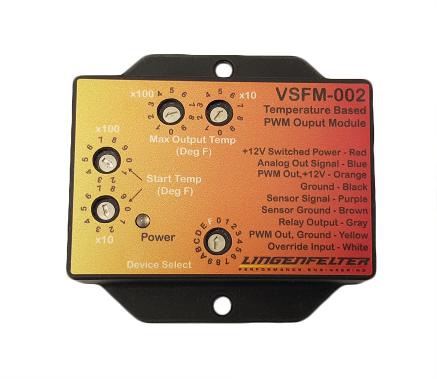
Great job on the fan setup. I do use a PWM fan setup inside my Autoexe airbox. I use a 300 cfm PWM controlled water resistance rated fan that uses a fan controller from Linqenfelter and the same Triumph air sensor we use in the uim placed in the airbox. It changes the fan speed automatically based on the air temp entering the airbox and determined by you based on start temp and full speed temp settings using pots on the controller. This is sort of a double ram air type setup given that my Abflug bumper feeds rammed in air directly into the Autoexe airbox too with the fan assisting particularly when in traffic or sitting at a light.
You could use the same setup on the intercooler fan which I didn't think of at the time. I did my intercooler fan setup first. One thing you could add to your current switching system is a button in the center console to control your two speeds. What I did is add a second fog light toggle switch in the center dummy switch area of the center console. I use the switch to change a double pole relay that chooses between the two fan speeds. That way you can change the fan speeds on the fly while driving and don't need to go under the hood.
Mike