
Initial IC Fan Observations

King of the Duct Tape
Joined: Feb 2001
Posts: 1,177
Likes: 0
From: PA
hmm, i wonder if that would be over kill or the ultimate in IC airflow, having a fan on either side one pushing one pulling. probably would really kill the airflow when they're not in use though.
when is your stuff coming in?
when is your stuff coming in?
King of the Duct Tape
Joined: Feb 2001
Posts: 1,177
Likes: 0
From: PA
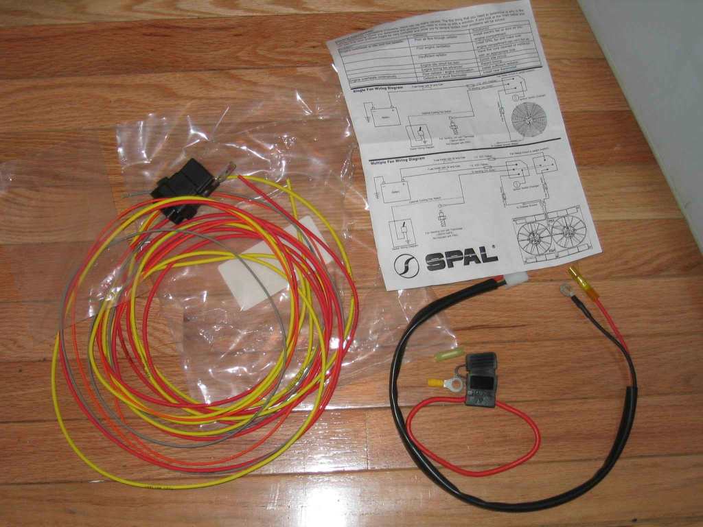
and the wiring i got. very good stuff. all the wires are labeled and the instructions seem very detailed. didn't look it over too much, i was just home for lunch.
Last edited by airborne; Apr 22, 2003 at 12:11 PM.
Thread Starter
Rotary Enthusiast
Joined: Oct 2002
Posts: 1,045
Likes: 1
From: Plano, TX
Took some pics of my setup. I didn't use the spal connectors - rather tie wraps. Worked awesome.
Here is the link
http://photos.yahoo.com/bc/jbg28/lst?.dir=/rx7&.view=t
Here is the link
http://photos.yahoo.com/bc/jbg28/lst?.dir=/rx7&.view=t
Originally posted by Brentis [B]Took some pics of my setup. I didn't use the spal connectors - rather tie wraps. Worked awesome.Here is the link
As you can see by a previous post I have all the air temp probes and gauge to do a accurate analysis of this feature under all conditions.
Those numbers will hopefully valuable to others.
Thread Starter
Rotary Enthusiast
Joined: Oct 2002
Posts: 1,045
Likes: 1
From: Plano, TX
I was a bit skeptical that the 2.5 amp one could pull 295 if the 6 amp one could pull 330cfm. On the flip side I was hopeful that the 6 amp one pulled more.. if the 2.5 amp pulled 295 cfm<shrug>

Sleeper
Joined: May 2002
Posts: 560
Likes: 0
From: North Dallas
Brentis, I don't see like you, any proportion of more amps and very little increase in CFM.
I still believe that somehow the CFM measure can't be that way off in the industry.
It just doesn't make sense to me.
Oh well, it looks good in there and lets wait for the test results.
Keep us posted Luv94Rx7.
I still believe that somehow the CFM measure can't be that way off in the industry.
It just doesn't make sense to me.
Oh well, it looks good in there and lets wait for the test results.
Keep us posted Luv94Rx7.
Originally posted by Brentis I was a bit skeptical that the 2.5 amp one could pull 295 if the 6 amp one could pull 330cfm. On the flip side I was hopeful that the 6 amp one pulled more.. if the 2.5 amp pulled 295 cfm<shrug>
Ken
PS: I just received my fan from UPS 10 minutes ago.
Thread Starter
Rotary Enthusiast
Joined: Oct 2002
Posts: 1,045
Likes: 1
From: Plano, TX
ok read this - and give your thoughts.
I'm still looking for my reference to amperage vs. cfm.
http://www.ofgb.org/reference/Comput...an%20guide.pdf
It relates to computer fans but same theories hold. - haven't finished it yet but sounds relevant.
I'm still looking for my reference to amperage vs. cfm.
http://www.ofgb.org/reference/Comput...an%20guide.pdf
It relates to computer fans but same theories hold. - haven't finished it yet but sounds relevant.
Thread Starter
Rotary Enthusiast
Joined: Oct 2002
Posts: 1,045
Likes: 1
From: Plano, TX
do you have adobe acrobat installed?
I need your email.
Another possible theory is that assuming motor efficiency is the same, the fan with the higher amperage may not be as susceptible to flow resistance.
Just guessing.
I need your email.
Another possible theory is that assuming motor efficiency is the same, the fan with the higher amperage may not be as susceptible to flow resistance.
Just guessing.
Sleeper
Joined: May 2002
Posts: 560
Likes: 0
From: North Dallas
Brentis will send you a PM with the e-mail address.
Sorry about that.
I don't know since I am a computer illiterate.
I am seaching in fan flow measurements efficiency and none mention amps. It is all in CFM.
Even the goverment with the standards of measurements that should mean something.
I will throw this into the mix, modern cars have electric fans and they do consume alot of electric power that's a given, but why they put a big fan and not a little one to reduce weight, drag, save space given same electrical draw needs.
I think that we are ALL right and that a fan cooling ability is a combination of all these factors (in no order of importance):
# of blades
Electrical draw
Size of blades (width and length)
Pitch of the baldes
Area of coverage of the fan motor
Thickness of the radiator
Opening in front of the radiator
Etc.....
What remains to be answered, is how can you hold down the intake temps when you are stuck in traffic with the fans on instead of increasing the intake temps?
How can we solve this one because I am stumped.

Thread Starter
Rotary Enthusiast
Joined: Oct 2002
Posts: 1,045
Likes: 1
From: Plano, TX
ok - try this then.. www.coolflow.com/intracooler/intercooler.htm
I did a quick and dirty test. I found that my shoulding before the IC is inferior. It sucks, at idle standing still, a lot of engine bay heat. I'll fix that with some duct tape or whatever in the future. I did an idle test for a long time(30+ minutes) in my garage. It was 70F degrees in the garage. With the fan on it dropped the temps after the IC by about 18F degrees compared to with the fan off. The PFC ECU Commander readings only went down 6F degrees. I think that is because the temp probe is right after the IC and the pipe to the engine heats up a lot standing still at idle and heats up the pipe and the PFC probe is just before the motor. I have to do alot more tests after I install it properly and fix the shroulding.
Thread Starter
Rotary Enthusiast
Joined: Oct 2002
Posts: 1,045
Likes: 1
From: Plano, TX
Another issue as stated by Maddog (or is it baddog) was that the probe for air intake temperature gets heat soaked and doesn't report accurate temps b/c it is buried by the engine. So even while the air temp *may* be cooler on the end of the probe the end of the probe is hot from the engine heat resulting in poor readings - plus it hurts performance as well - as it isn't getting the right a/f

Rotary Enthusiast
Joined: Dec 2001
Posts: 1,209
Likes: 6
From: Delaware
Originally posted by Radical Rotary Avantgard
I am seaching in fan flow measurements efficiency and none mention amps. It is all in CFM....................
......What remains to be answered, is how can you hold down the intake temps when you are stuck in traffic with the fans on instead of increasing the intake temps?
How can we solve this one because I am stumped.
for IC fans, one key issue is pressure drop, or static pressure rating. note in this spal link, rated flow drops by 50% with only 1/2" of water column pressure drop.
http://www.spal-usa.com/pdfs/6.5Fans.pdf
{note that the perma-cool 8" flow is only estimated to be 800 cfm ( at zero pressure drop). I doubt this rating, based on amps and size.}
For a back mounted fan, this drop is the static pressure under the hood, plus any vacuum created at the fan front. with no stand-off/shroud, like stock fan, air is pull thru an annular ring of area that is full of fins and tubes, so vacuum is very likely. if fan is just stood off 1/3" or so, it will recirc around the perimeter, for less vacuum but less flow thru core.
to hold down temps in traffic, best to use a shroud with stand off, and at least for dual 8" fans, make sure rad fan is on at low when IC fans are on. But with slow intake air flow, and radiant/conductive heating of the intake manifold and piping exit the IC, don't expect the big chill at the IAT sensor. But there is still merit in precooling the mass of the IC core (and exit tank), so when u do get going, the IC will quickly cool the charge.


Senior Member
Joined: Apr 2001
Posts: 334
Likes: 0
From: Boston, MA, USA
Pics!!!
Let's get back to basics - words hurt head.
This is the setup I described back - oo - on page 1 or so. You can see the fan, which was mounted with the nylon mounting straps that harmlessly go through the IC.
Above the fan is the temp sensor (a bit big, but it works)
Poking out behind the IC (well, in front of it) by the fuse box you can see the top of my control box - with the green LED.