HOW TO: Make your untuned PFC basemap safer/idle better (no Datalogit needed)


 11-12-10, 03:37 PM
#52
Planning my come back
iTrader: (7)

Join Date: Feb 2003
Location: Austin, Tx
Posts: 3,393
Likes: 0
Received 0 Likes
on
0 Posts
Okay figured it out and got the car going. The idle learning didn't fix my idle surging issue so I will look into that another way (mechanically) but the ignition changes and adding more fuel sure made he car run a lot better. Not faster but smoother.
04-13-11, 10:11 PM
#55
Super Raterhater
iTrader: (6)
Join Date: Dec 2001
Location: NY, MA, MI, OR, TX, and now LA or AZ!
Posts: 10,624
Likes: 0
Received 2 Likes
on
2 Posts
arghx, don't suppose you'd happen to have a snapshot of your 'safer' Igt map, as I see you have both the old and new Igl's, but none at all of the trailings.
04-14-11, 11:11 AM
#56
I'm not really going to expand upon the advice I have given about trailing timing here because it is beyond the scope of this thread. If you have further questions about setting trailing timing I suggest you go to the PFC sub forum or PM cewrx7r1 about his tuning group.
06-03-11, 12:06 PM
#62
How O2 Feedback Works
Thanks to JhnRx7, a member of the tuning group, for his help on this. I'm not going to go too in-depth here but I have covered this topic more extensively in the PFC group. O2 feedback is still being explored at this time.
With O2 feedback active, the PFC will continuously change the primary injector pulsewidth in order to keep the stock o2 sensor voltage oscillating around the switchpoint of .45 volts. On a narrowband sensor .45 volts roughly corresponds to lambda =1 or 14.7:1 AFR.
Tuners disable O2 feedback completely for a couple reasons, but the more important one is the fact that using O2 feedback at the wrong rpm and load point can lead to surging and other problems. I have previously said that everyone should turn off O2 feedback. Well with the Apex'i default map and a mildly modified setup the feedback should actually work fine and not cause any surging. There are three main reasons why one would want to keep O2 feedback on:
1) It can respond to changes in the weather and engine conditions so that AFR's don't fluctuate too much in INJ map cells where it is active
2) Anecdotally there appears to be some improvement in tip-in and transient response
3) Using o2 feedback will give optimum emissions under some driving conditions
Some of the O2 feedback control logic is still a bit mysterious, but generally speaking it operates when:
� Full range TPS (VTA1) reads > 1.0 volts
� Coolant temperature is > 60C
� INJ value in the current cell of the fuel map is between 1.0 and 1.047. That 1.047 value can be adjusted in the Datalogit and some tuners just set it to 1.0 .
� Calculated injector pulse during feedback is still above the minimum pulsewidth limit. This limit is a well-known limitation of the Power FC. It varies a little bit but roughly 2.5 msec is the lowest pulsewidth unless fuel is being completely cut for deceleration.

That is a log of O2 feedback in action. The fuel injection (bottom blue line) oscillates in response to the narrowband o2 sensor signal (red line) and the AFR (purple line) stays between 14:1 and 15:1, just like when your mom's Camry is driving around.
It is possible to use O2 feedback on an engine without a cat and airpump (a recalc'd INJ map) but that requires a Datalogit and it goes beyond the scope of this thread.
Thanks to JhnRx7, a member of the tuning group, for his help on this. I'm not going to go too in-depth here but I have covered this topic more extensively in the PFC group. O2 feedback is still being explored at this time.
With O2 feedback active, the PFC will continuously change the primary injector pulsewidth in order to keep the stock o2 sensor voltage oscillating around the switchpoint of .45 volts. On a narrowband sensor .45 volts roughly corresponds to lambda =1 or 14.7:1 AFR.
Tuners disable O2 feedback completely for a couple reasons, but the more important one is the fact that using O2 feedback at the wrong rpm and load point can lead to surging and other problems. I have previously said that everyone should turn off O2 feedback. Well with the Apex'i default map and a mildly modified setup the feedback should actually work fine and not cause any surging. There are three main reasons why one would want to keep O2 feedback on:
1) It can respond to changes in the weather and engine conditions so that AFR's don't fluctuate too much in INJ map cells where it is active
2) Anecdotally there appears to be some improvement in tip-in and transient response
3) Using o2 feedback will give optimum emissions under some driving conditions
Some of the O2 feedback control logic is still a bit mysterious, but generally speaking it operates when:
� Full range TPS (VTA1) reads > 1.0 volts
� Coolant temperature is > 60C
� INJ value in the current cell of the fuel map is between 1.0 and 1.047. That 1.047 value can be adjusted in the Datalogit and some tuners just set it to 1.0 .
� Calculated injector pulse during feedback is still above the minimum pulsewidth limit. This limit is a well-known limitation of the Power FC. It varies a little bit but roughly 2.5 msec is the lowest pulsewidth unless fuel is being completely cut for deceleration.
That is a log of O2 feedback in action. The fuel injection (bottom blue line) oscillates in response to the narrowband o2 sensor signal (red line) and the AFR (purple line) stays between 14:1 and 15:1, just like when your mom's Camry is driving around.
It is possible to use O2 feedback on an engine without a cat and airpump (a recalc'd INJ map) but that requires a Datalogit and it goes beyond the scope of this thread.
06-03-11, 04:55 PM
#63
Moderator
iTrader: (3)
Join Date: Mar 2001
Location: https://www2.mazda.com/en/100th/
Posts: 30,835
Received 2,603 Likes
on
1,847 Posts
on the stock ECU the feedback "zone" has rpm limits, does the power FC? or does it just go by injector duty.
 08-15-11, 11:52 PM
#65
Monitoring Sequential Turbo Transition
Sequential turbo transition can be monitored on your Commander using the etc. --> sensor/sw check screen.

When the engine is running on the primary turbo only, Charge Control "CCN" will be ON and Turbo Control "TCN" will be "OFF." After transition, the inverse will be true: CCN will be OFF and TCN will be "ON." Switching these solenoids releases vacuum on the Charge Control valve (supplying boost pressure from the compressor outlet instead) while providing pressure and vacuum from their respective tanks to the turbo control actuator.
How Sequential Turbo Transition is Determined
On the stock ECU, sequential turbo transition is staged based on rpm, throttle position, and gear position (see Tashima, "Sequential Twin Turbocharged Rotary Engine of the Latest Rx-7, 1994). On the PFC, sequential turbo transition is staged based only on rpm and throttle position. Here are the default settings, accessible only with a Datalogit:
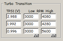
The left column is full range TPS voltage (VTA1). The right column ("Turbo Transition High" is the rpm at which both turbos come on line (CCN switches OFF and TCN switches ON) during acceleration. The PFC will keep the engine in non sequential mode until rpms fall below the value in the middle column, "Turbo Transition Low." A technical term for this "Turbo Transition Low" is a hysteresis setting.
IMO the default values of 3000rpm for Turbo Transition Low are not optimal for most applications. What can happen is that you initially accelerate and the engine feels responsive, but after a gear change it suddenly feels sluggish. Sometimes that's an actual mechanical problem (bad check valve or something) but it could be the result of the 3000rpm Turbo Transition Low settings. The charts below illustrate:

This is a log from an autocross event. The driver initially lets off the throttle, but here the PFC has kept the engine in non sequential mode because rpms never fell below 3000rpm between gear changes. You know it's non sequential because Turbo control (TCN) is ON, a "1" and charge control (CCN) is OFF, a "0." The wastegate is controlling boost (blue line, where 255 = 100% solenoid duty) and the pre control is allowed to be wide open (red line, seen here at 0). When the throttle (green line) opens, boost/PIM (orange) builds relatively slowly and peak boost doesn’t come until around 5000rpm which is spool you would expect from a big-ish single turbo.
Changing the "Turbo Transition Low" values can help this. I prefer about 3500rpm for all three values. While these settings are not accessible using the Commander, you can still view the status of your turbo transition using the sensor/sw check screen.
Sequential turbo transition can be monitored on your Commander using the etc. --> sensor/sw check screen.
When the engine is running on the primary turbo only, Charge Control "CCN" will be ON and Turbo Control "TCN" will be "OFF." After transition, the inverse will be true: CCN will be OFF and TCN will be "ON." Switching these solenoids releases vacuum on the Charge Control valve (supplying boost pressure from the compressor outlet instead) while providing pressure and vacuum from their respective tanks to the turbo control actuator.
How Sequential Turbo Transition is Determined
On the stock ECU, sequential turbo transition is staged based on rpm, throttle position, and gear position (see Tashima, "Sequential Twin Turbocharged Rotary Engine of the Latest Rx-7, 1994). On the PFC, sequential turbo transition is staged based only on rpm and throttle position. Here are the default settings, accessible only with a Datalogit:
The left column is full range TPS voltage (VTA1). The right column ("Turbo Transition High" is the rpm at which both turbos come on line (CCN switches OFF and TCN switches ON) during acceleration. The PFC will keep the engine in non sequential mode until rpms fall below the value in the middle column, "Turbo Transition Low." A technical term for this "Turbo Transition Low" is a hysteresis setting.
IMO the default values of 3000rpm for Turbo Transition Low are not optimal for most applications. What can happen is that you initially accelerate and the engine feels responsive, but after a gear change it suddenly feels sluggish. Sometimes that's an actual mechanical problem (bad check valve or something) but it could be the result of the 3000rpm Turbo Transition Low settings. The charts below illustrate:
This is a log from an autocross event. The driver initially lets off the throttle, but here the PFC has kept the engine in non sequential mode because rpms never fell below 3000rpm between gear changes. You know it's non sequential because Turbo control (TCN) is ON, a "1" and charge control (CCN) is OFF, a "0." The wastegate is controlling boost (blue line, where 255 = 100% solenoid duty) and the pre control is allowed to be wide open (red line, seen here at 0). When the throttle (green line) opens, boost/PIM (orange) builds relatively slowly and peak boost doesn’t come until around 5000rpm which is spool you would expect from a big-ish single turbo.
Changing the "Turbo Transition Low" values can help this. I prefer about 3500rpm for all three values. While these settings are not accessible using the Commander, you can still view the status of your turbo transition using the sensor/sw check screen.
 09-16-11, 08:02 AM
#67
The PFC maps use absolute pressure in kg/cm^2, which is a pretty unusual. Most other engine management systems using absolute pressure will use kilopascals. Here are some of the default timing maps that come with the PFC but converted into relative pressure:
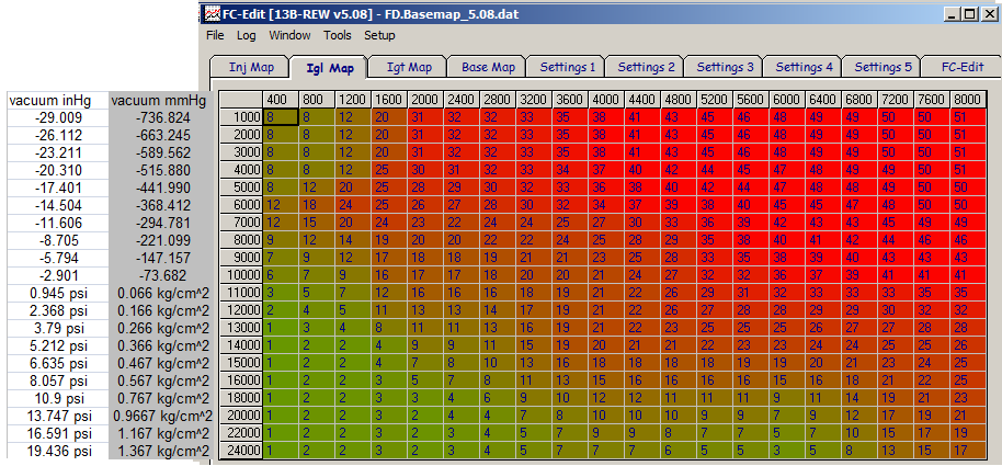
That's from PFC version 5.08 which is what most PFC's come with.
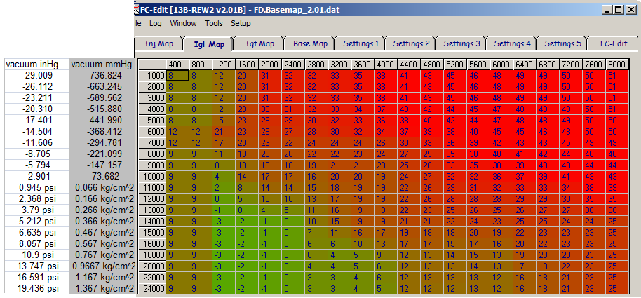
That's from an early version of the PFC, 2.08
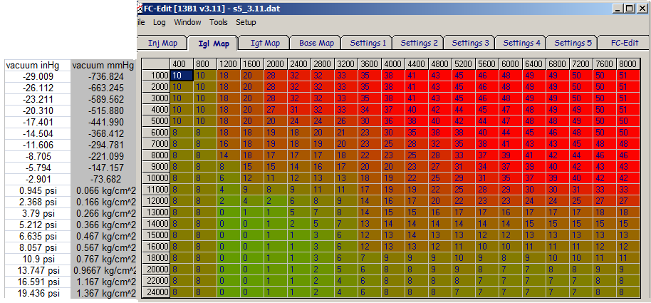
That's from the version for the FC series 5 Turbo.
The trailing/split maps that came with the PFC are kinda ugly, but here are a couple:
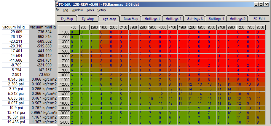
that's the regular 5.08 trailing/split map that most PFC's come with, the one I recommended you add split to.

The above split map from early PFC's, version 2.08, is better in terms of safety but it does have that weird spot at 7600 rpm.
These maps don't show the reference labels (N1, P1 etc) Remember that the PFC counts horizonally and vertically from the origin in the upper left corner. So the upper left corner is N1, P1 and the bottom right corner is N20, P20. Also keep in mind that your actual pressure readings will depend on the MAP sensor scaling and your altitude. The stock FD MAP sensor with the default calibration tends to read pressure a little bit low, usually about 1psi low by full boost.
That's from PFC version 5.08 which is what most PFC's come with.
That's from an early version of the PFC, 2.08
That's from the version for the FC series 5 Turbo.
The trailing/split maps that came with the PFC are kinda ugly, but here are a couple:
that's the regular 5.08 trailing/split map that most PFC's come with, the one I recommended you add split to.
The above split map from early PFC's, version 2.08, is better in terms of safety but it does have that weird spot at 7600 rpm.
These maps don't show the reference labels (N1, P1 etc) Remember that the PFC counts horizonally and vertically from the origin in the upper left corner. So the upper left corner is N1, P1 and the bottom right corner is N20, P20. Also keep in mind that your actual pressure readings will depend on the MAP sensor scaling and your altitude. The stock FD MAP sensor with the default calibration tends to read pressure a little bit low, usually about 1psi low by full boost.
 11-24-11, 09:45 PM
#69

The PFC maps use absolute pressure in kg/cm^2, which is a pretty unusual. Most other engine management systems using absolute pressure will use kilopascals. Here are some of the default timing maps that come with the PFC but converted into relative pressure:
These maps don't show the reference labels (N1, P1 etc) Remember that the PFC counts horizonally and vertically from the origin in the upper left corner. So the upper left corner is N1, P1 and the bottom right corner is N20, P20. Also keep in mind that your actual pressure readings will depend on the MAP sensor scaling and your altitude. The stock FD MAP sensor with the default calibration tends to read pressure a little bit low, usually about 1psi low by full boost.
These maps don't show the reference labels (N1, P1 etc) Remember that the PFC counts horizonally and vertically from the origin in the upper left corner. So the upper left corner is N1, P1 and the bottom right corner is N20, P20. Also keep in mind that your actual pressure readings will depend on the MAP sensor scaling and your altitude. The stock FD MAP sensor with the default calibration tends to read pressure a little bit low, usually about 1psi low by full boost.
you say its safer to use the older map , but the older map seems to be advanced alot more then the new map ? so wouldn't it be the less safe one maybe causing some knock .. or am I missing something , is it completely different since the leading is well taking the lead ?
Last edited by Tem120; 11-24-11 at 10:06 PM.
11-25-11, 01:05 AM
#70
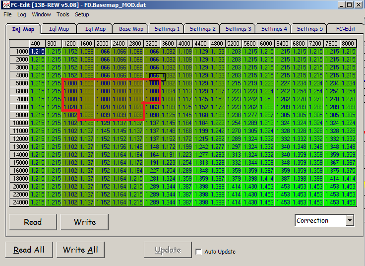
You might be a little mixed up here, partly due to some trivial comments I have made previously. Here's what you need to know: On the 5.08 Power FC default map from Apex'i, which is what 95% or more of these units come with, you can increase the safety of the tune by retarding the trailing igntion. Retarding the trailing ignition is the same as increasing the split. Split = Leading timing - trailing timing
If you have the Commander only, you would go into the IGT map and subtract 4 degrees in the area I specified. That decreases timing advance on the trailing (retards it) and increases the separation between the leading and trailing plugs (split goes up). The Commander doesn't calculate split for you automatically. If you have a Datalogit box with FC-Edit software it will automatically show the split if you check the box to do so.
If you have the Commander only, you would go into the IGT map and subtract 4 degrees in the area I specified. That decreases timing advance on the trailing (retards it) and increases the separation between the leading and trailing plugs (split goes up). The Commander doesn't calculate split for you automatically. If you have a Datalogit box with FC-Edit software it will automatically show the split if you check the box to do so.
11-25-11, 02:21 AM
#71
You might be a little mixed up here, partly due to some trivial comments I have made previously. Here's what you need to know: On the 5.08 Power FC default map from Apex'i, which is what 95% or more of these units come with, you can increase the safety of the tune by retarding the trailing igntion. Retarding the trailing ignition is the same as increasing the split. Split = Leading timing - trailing timing
If you have the Commander only, you would go into the IGT map and subtract 4 degrees in the area I specified. That decreases timing advance on the trailing (retards it) and increases the separation between the leading and trailing plugs (split goes up). The Commander doesn't calculate split for you automatically. If you have a Datalogit box with FC-Edit software it will automatically show the split if you check the box to do so.
If you have the Commander only, you would go into the IGT map and subtract 4 degrees in the area I specified. That decreases timing advance on the trailing (retards it) and increases the separation between the leading and trailing plugs (split goes up). The Commander doesn't calculate split for you automatically. If you have a Datalogit box with FC-Edit software it will automatically show the split if you check the box to do so.
ICC!! so you dont retard the leading at all its all on the trailing! IC IC IC!
and leave the leading alone , even at over 10 PSI? or is retarding the trailing a reliability mod even at stock 10 psi? I might have missed that part lol sorry
but thanks for clarifying this .
11-25-11, 08:42 AM
#72
You could retard the leading but that's going to increase exhaust temperatures which can be detrimental to the life of components. IMO it's not necessary for a healthy, mildly modified FD running the default Apex'i map and using premium fuel.
 01-13-12, 09:53 AM
#74

Regarding cruise surges:
I read that Chuck advised to change these cells on the INJ MAP instead of turning off O2 Feedback. I've seen him post several times about adjusting N3-N8 / P4-P7, but I have never seen his map to compare.
What direction does he recommend adjusting these 1.0 values? Up or down?
Do you recommend changing these values to eliminate the cruise surging?
Or do you recommend changing the cells that use the O2 feedback? What cells would those be?
