
Fuel cut at 26 PSI. enjoy

and i watched your other videos, nice real world insight for regular people. maybe i will show it to my stepson since he really needs some sort of motivation to do something, anything.
:-) thanks. i try to keep the mistakes in my videos because its more fun to show them. I seem to get further in life without the ego. haha
Its beautiful how fast my car builds boost though. I thought i would have to street port it etc. Really opened the intake up and it made a huge difference.


Explain exactly how your lines are routed. Draw a diagram if necessary. I think a plumbing change would help you here. Some spiking in cold weather with the PFC boost control is a known issue, because unfortunately you don't have really precise control over the duty cycle during spool up.
I'll ms paint a diagram and post it. Quickly I have manifold pressure plugged into NC and COM to the wastegate.
As much as I don't want to admit this late night realization, I have the wastegate lines plugged into actual manifold pressure not turbo outlet pressure. Can the butterfly valves influence my problem as well?
As much as I don't want to admit this late night realization, I have the wastegate lines plugged into actual manifold pressure not turbo outlet pressure. Can the butterfly valves influence my problem as well?
Routing after the butterflies on the manifold is ok is some situations. There are 4 basic ways to do it.
top port- compressor
side port- compressor
top-Compressor
side-Manifold
top- manifold
side- comp
top- manifold
side-maniflold
Each of these 4 ways will produce slightly different results. Think about the way the WG works and the pressure drop across the Ic and you will figure it out. I find straight off the compressor is the most consistent
Arghx knows alot about using the PFC to control boost. He has some good write ups on here, I think he's the one that figured this out.
I personally found a seperate EBC more consistant but many seemed to have worked it out with the PFC.

I am running pfc boost control with a greddy solenoid, tial v44 on a 35r and find the best results using compressor outlet to the side port and manifold pressure to the solenoid and top port. Using manifold pressure to the side port resulted in several psi higher minimum boost on my setup.
I see your MS Paint diagram and raise you 2  Refer to the decision matrix I put together below:
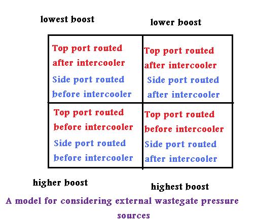
So try this modification of your above diagram,

while considering the following [somewhat oversimplified] diagram:
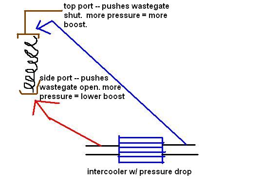
There's two reasons why I believe my suggested plumbing change will help.
1) time delay--due to the travel time, pressure will reach the lower diaphragm chamber before the upper diaphragm chamber, meaning a greater tendency to open wastegate
2) pressure drop--at a hypothetical 100% solenoid duty the upper diaphragm chamber will have, relatively speaking, less pressure operating on it than the lower chamber due to the pressure drop from sourcing it at the manifold.
Remember that conventional pneumatic boost control (as opposed to electronic wastegates for example) could be broken down into following elements:
1) hot side plumbing --wastegate valve and manifold design, turbine housing, etc
2) pneumatics & related hardware-- wastegate actuator (design of diaphram), various hoses and orifices
3) electronic hardware: # and configuration of pneumatic valves (solenoid or stepper type here)
4) software--whatever control logic is used to determine how the solenoid or motor will be activated (does it have a boost target? does it have rpm based adjustment?)
5) tuning--the actual settings you pick within the framework of the software.
All of these elements work together. So if you go with an external controller you are getting certain elements from the above list. Say you buy a Greddy Spec II. You are getting a particular type of solenoid (one 3-port). You are buying a particular type of software in the embedded control unit.
In the Greddy example, those are the only things that are truly fixed. You can run whatever hoses you want with that. You can put whatever settings you want within the constraints of the on-board software. You can use whatever wastegate valve, spring pressure, intercooler, orifices (restricter pills), Tee's, whatever. You just have to know what you're doing. You must understand boost control as a system. ok, end of lecture... hope to those of you who got through that... check out this thread if you haven't:
https://www.rx7club.com/3rd-generati...-chart-952767/
So try this modification of your above diagram,
while considering the following [somewhat oversimplified] diagram:
There's two reasons why I believe my suggested plumbing change will help.
1) time delay--due to the travel time, pressure will reach the lower diaphragm chamber before the upper diaphragm chamber, meaning a greater tendency to open wastegate
2) pressure drop--at a hypothetical 100% solenoid duty the upper diaphragm chamber will have, relatively speaking, less pressure operating on it than the lower chamber due to the pressure drop from sourcing it at the manifold.
Remember that conventional pneumatic boost control (as opposed to electronic wastegates for example) could be broken down into following elements:
1) hot side plumbing --wastegate valve and manifold design, turbine housing, etc
2) pneumatics & related hardware-- wastegate actuator (design of diaphram), various hoses and orifices
3) electronic hardware: # and configuration of pneumatic valves (solenoid or stepper type here)
4) software--whatever control logic is used to determine how the solenoid or motor will be activated (does it have a boost target? does it have rpm based adjustment?)
5) tuning--the actual settings you pick within the framework of the software.
All of these elements work together. So if you go with an external controller you are getting certain elements from the above list. Say you buy a Greddy Spec II. You are getting a particular type of solenoid (one 3-port). You are buying a particular type of software in the embedded control unit.
In the Greddy example, those are the only things that are truly fixed. You can run whatever hoses you want with that. You can put whatever settings you want within the constraints of the on-board software. You can use whatever wastegate valve, spring pressure, intercooler, orifices (restricter pills), Tee's, whatever. You just have to know what you're doing. You must understand boost control as a system. ok, end of lecture... hope to those of you who got through that... check out this thread if you haven't:
https://www.rx7club.com/3rd-generati...-chart-952767/
I will definitely try this tomorrow. As always very appreciated. I have a firm grasp of the system except I always trip up and thing duty cycle is the wastegate operation not the solenoid operation so I'm thinking the wastegate is opening and closing repeatedly at the duty cycle percentage lol
Another thing I noticed in my logs, the WG stays at 1 through idle and cruising. Once I get to near WOT I see it log 243 consistently until I let off the pedal. Never once a variation on that number changing boost levels or duty cycles.
Another thing I noticed in my logs, the WG stays at 1 through idle and cruising. Once I get to near WOT I see it log 243 consistently until I let off the pedal. Never once a variation on that number changing boost levels or duty cycles.

Joined: Mar 2001
Posts: 31,837
Likes: 3,234
From: https://www2.mazda.com/en/100th/
i had a motor come apart (spectacularly) @the rev limiter for ~30 seconds, and after consulting with some of the old school racing people, the rev limiter can cause more harm than good, if you hit it for a long time and its at too high of an rpm.
the next engine was run with no limiter, to 9400rpm with no problem.
the rev limiter is different from boost cut though. at the stock rpm, its totally fine to hit the limiter too, but its bad to pass start finish, hit the limiter and then stay on it until turn 3.... at higher than stock rpm, its probably better to turn it off
yes, high RPM hard rev cuts are bad, the e-shaft will start to deflect and bounce the rotors off the tips to rotor housings and from there other nasty things can happen(stat gears strip). if you're lucky you just pinch a few seals. a 3 piece shaft with center bearing would alleviate the issue but 2 piece shafts IMO add a stress point and will not handle the power of a single piece shaft.
similar reasoning why turbos fail from 2 steps, the shaft/rotor is stalling and then power applied rapidly. without ignition to keep the engine rotating in a forward motion the momentum can't carry it up to and beyond TDC without creating slack. the less peak pressure the engine makes the less of a problem it is, ie high horsepower large turbo setups pushing beyond 8k it's best to map a cut in(dump in all fuel and retard ignition) versus using even soft cuts. plugs will take a beating but better than a $2-3k engine/turbo.
similar reasoning why turbos fail from 2 steps, the shaft/rotor is stalling and then power applied rapidly. without ignition to keep the engine rotating in a forward motion the momentum can't carry it up to and beyond TDC without creating slack. the less peak pressure the engine makes the less of a problem it is, ie high horsepower large turbo setups pushing beyond 8k it's best to map a cut in(dump in all fuel and retard ignition) versus using even soft cuts. plugs will take a beating but better than a $2-3k engine/turbo.
Last edited by RotaryEvolution; Sep 25, 2012 at 12:09 PM.
I will definitely try this tomorrow. As always very appreciated. I have a firm grasp of the system except I always trip up and thing duty cycle is the wastegate operation not the solenoid operation so I'm thinking the wastegate is opening and closing repeatedly at the duty cycle percentage lol
Another thing I noticed in my logs, the WG stays at 1 through idle and cruising. Once I get to near WOT I see it log 243 consistently until I let off the pedal. Never once a variation on that number changing boost levels or duty cycles.
Another thing I noticed in my logs, the WG stays at 1 through idle and cruising. Once I get to near WOT I see it log 243 consistently until I let off the pedal. Never once a variation on that number changing boost levels or duty cycles.
No I didn't. I saw in your previous posts regarding that. But I also had manifold pressure plugged into NO so I was multiple problems deep. Sprinkling here. As it might be near you too but I'll check on that ASAP.
Here's what you should try, just to summarize:
NC port on solenoid: pressure source after intercooler
COM port: connected to top port of wastegate
NO port: open to atmosphere
so on the wastegate we have:
top port: connected to COM port of solenoid, as I mentioned above
side port: connected directly to a pressure source before the intercooler
In the Power FC datalogit Setting 1 tab, check the box for "Sequential Turbo Control" . Set all turbo transition high values to 2000, and all low values to 1800.
arghx you are a god amongst men. Seriously, i owe you dinner or drinks or something.
For future thread readers (most likely myself when i accidentally wipe out all of my PowerFC settings) once i put the manifold pressure line to NC (Normally Closed) the system was ready for the correct Power FC settings.
I then did as instructed and under Settings 1 page in the Dataloggit i set Turbo Transition values (all 3 sets) Low RPM = 1800 and High RPM = 2000
I ultimately set my boost control to 1.5 (after testing lower levels) and duty cycle to 50 and it hits 1.5 bar (~22 PSI) perfect.
Im assuming if i fine tune duty cycle i can increase or decrease how fast i get to 22 PSI.

Thread
Thread Starter
Forum
Replies
Last Post
alphawolff
1st Generation Specific (1979-1985)
17
Nov 17, 2015 05:57 PM
armans
3rd Generation Specific (1993-2002)
5
Aug 15, 2015 09:08 PM

