When you click on links to various merchants on this site and make a purchase, this can result in this site earning a commission. Affiliate programs and affiliations include, but are not limited to, the eBay Partner Network.
While researching a part number to a diode from the Instrument Cluster Flex Print, I noted a similarity with ZD8 and ZD9 on the Speedo board. I propose the part number stenciled on ZD8 and ZD9 will match D8 from the flex print. Follow this link to read about my research on Flex Print's D8: Post #7.
I have some more information concerning the Diodes and Zener Diodes on the Speedometer board. I removed these diodes from a board and attempted to read their markings. Unfortunately, these components were abraded so the exposed surface is unreadable. This is what I found:
Diodes:
D1: *No markings*
D2: 4K or K4
D3: 4K or K4
D4: 4K or K4
D5: 4K or K4
Zener Diodes:
ZD1: 30 *Partial*
ZD2: 30 (line 1) 2 (line 2)
ZD3: 3 *Partial*
ZD4: 1N4742A, DigiKey P/N: 1N4742AFSCT-ND, Radio Shack P/N: 2760563 (this part number worked for another Member)
ZD5: 5 *Partial*, a second diode had "A" and "3" marked on it. It may be "A3" *Partial*?
ZD6: PZ627 preceded by 18A or 17B (observed from 2 different Speedo boards)
ZD7: *Illegible*
ZD8: 3 *Partial*, there may also be a possibility of a diode from Post #51 (above) to match this one.
ZD9: 3 *Partial*, a second diode had "A43" marked on it, there may also be a possibility of a diode from Post #51 (above) to match this one.
ZD10: 30 *Partial* could be similar to ZD2, a second diode only had "2" marked on it. Combined the 2 diodes and it would be 30 (line 1) 2 (line 2)
Are there any other Electrical Engineers on the forum who could help identify these diode markings?
Here are some additional photos to document my findings in Post #52, above. Does anyone see anything else different? Read the captions on each photo for reference designations.
Cheers,
George
D2 thru D5 part a. Marked "4K"
D2 thru D5 part b. Marked "4K"
ZD1 part a. Marked "30"
ZD1 part b. Marked "2"? This number is illegible and note the abrasion on the glass surface.
You could use it. But do you really need 6 pieces? Maybe 2 pieces in case there is an accident while soldering. The bigger questions to ask: what other components need to be replaced? How much damage is on the board? Based upon my experience, C3 will not be the only cap that needs replacement. For help in diagnosing/troubleshooting the speedo board check out this link: Troubleshooting the FD Speedometer-Odometer-Tachometer Circuit Board
To answer your question: ESR = Equivalent Series Resistance. More info can be found here: Capacitors and ESR Or find out more through a google search.
Cheers,
George
Thx George!
The odo/speedo board is pretty clean other than that cap (see pic of c3)
. I expected more as well... i will run another look this morning.. just in case..
Wow! That looks spectacular! Please inspect the rest of the board for possible damage and other leaked capacitors. There are some physical observations to tell if a capacitor is bad. Pay attention to each cap's top & bottom - if it is bowed then it's failing. Additionally, if any capacitor looks swollen (sides bulging) then it too is suspect and should be replaced. The cylindrical sidewalls should be straight and parallel to one another, the top and bottom lids should be flat. However, a visual inspection is not the sole method to identify bad capacitors.
Good to see that your odo is fixed. How is it holding up? Did you only replace C3? Where there other components that you identified as bad?
Cheers,
George
So far, so good. Took it for a long drive and it worked just great! It was just C3 that I could find... so figured I would leave well enough alone and not risk cherry picking random components. I did spend some time making sure it was clean (including the C3 pads) before soldering the new cap in place. Will report back if it decides to fail... fingers crossed it wont!
I have some more information concerning the Diodes and Zener Diodes on the Speedometer board. I removed these diodes from a board and attempted to read their markings. Unfortunately, these components were abraded so the exposed surface is unreadable. This is what I found:
Diodes:
D1: *No markings*
D2: 4K or K4
D3: 4K or K4
D4: 4K or K4
D5: 4K or K4
Zener Diodes:
ZD1: 30 *Partial*
ZD2: 30 (line 1) 2 (line 2)
ZD3: 3 *Partial*
ZD4: 1N4742A, DigiKey P/N: 1N4742AFSCT-ND, Radio Shack P/N: 2760563 (this part number worked for another Member)
ZD5: 5 *Partial*, a second diode had "A" and "3" marked on it. It may be "A3" *Partial*?
ZD6: PZ627 preceded by 18A or 17B (observed from 2 different Speedo boards)
ZD7: *Illegible*
ZD8: 3 *Partial*, there may also be a possibility of a diode from Post #51 (above) to match this one.
ZD9: 3 *Partial*, a second diode had "A43" marked on it, there may also be a possibility of a diode from Post #51 (above) to match this one.
ZD10: 30 *Partial* could be similar to ZD2, a second diode only had "2" marked on it. Combined the 2 diodes and it would be 30 (line 1) 2 (line 2)
Are there any other Electrical Engineers on the forum who could help identify these diode markings?
Cheers,
George
I reviewed another Speedo board today and verified some of the body markings on the Zener Diodes. The components were examined on the board and with a 16x Jewelers Loupe. Here is the latest update:
Zener Diodes:
ZD1: 30 2
ZD2: 30 2
ZD3: 1 C
ZD4: 4. (decimal point next to the "4"), another member successfully used 1N4742A, DigiKey P/N: 1N4742AFSCT-ND, Radio Shack P/N: 2760563
ZD5: .1 (decimal point appears to be in front of the "1"), previous diodes marked as 5 *Partial*, a second diode had "A" and "3" marked on it. It may be "A3" *Partial*?
ZD6: PZ627 preceded by 18A, 17B, 24B (observed from 3 different Speedo boards)
ZD7: 5.A (decimal point appears to be after the "5")
ZD8: A, previous diodes marked as 3 *Partial*, possible match of diode from Post #51.
ZD9: .3 (decimal point marked before the "3"), previous diodes marked 3 *Partial*, a second diode had "A43" marked on it, possible match of diode from Post #51.
ZD10: 30 2, same as ZD1 and ZD2 markings.
I had no luck in identifying replacement parts. Does anyone else have information available?
Spyder, any luck with your replacements for ZD5 and ZD7?
I did a bit more digging to find a replacement for TR4. Based upon my research, I may have found a suitable substitute. Here's the skinny:
Power Transistors:
TR4: B1217 (Obsolete Part Number, no known replacement)
This part number crossed to 2SB1217, thanks to ALIENR2 for the initial leg work noted on this thread: Troubleshooting FD Speedo Post 27
Now, the original cannot be sourced from Mouser or Digikey. However, it can be purchased from ebay sellers. Consider these to be New Old Stock (NOS). So that is an option.
Moving on, the 2SB1217 part number crossed to a substitute part number: NTE185. The original and substitute is a PNP transistor. The substitute does has higher maximum specifications when compared to the original but I believe this would be a good choice when the original cannot be sourced. The datasheets for the original and substitute are attached for your reference and comparison. It is important to note the datasheet for NTE185 is actually for its NPN version, NTE184 so the voltage polarities are opposite from the 2SB1217 datasheet. This is because NTE185 is complementary to NTE184.
***UPDATE: This information is out of date but remains for historical tracking purposes. Please refer to the most recent post that reflects the most up-to-date and accurate part number lists.***
Here is an updated parts list for the entire Speedometer circuit board. In short, this update adds a source P/N for IC7 and TR3, alternate P/N's for TR7 and TR8, an alternate diode body marking for D3, and listed the Surface Mounted Devices (SMDs) with their values that are on the back side of the circuit board.
Capacitors: (Values shown)(Temp on all Caps: 105*C)
C1: 10uF, 50V, DigiKey P/N: 493-1890-ND
C2: 47uF, 25V, DigiKey P/N: P5539-ND
C3: 1000uF, 6.3V, DigiKey P/N: P10199-ND
C4: 1uF, 50V, DigiKey P/N: 565-1332-ND
C6: 1uF, 50V, DigiKey P/N: 565-1332-ND
C9: R33 (line 1) BP (line 2), 50V, *P/N search suggests 33uF*
C11: 2.2uF, 50V, DigiKey P/N: P13462-ND
C12: 10uF, 50V, DigiKey P/N: 493-1890-ND
C13: 1uF, 50V, DigiKey P/N: 565-1332-ND
C15: 0.015uF, 50V, Mouser P/N: 80-MMK5153J50J01TA18 *CAUTION: Refer to Post #25!*
C16: 2.2, 50V, *Need capacitance value, could be uF or pF*
C17: 1, 50V, *Need capacitance value, could be uF or pF*
Note 1: Must use SOT-89 to Through Hole Adapter with SMD type of IC2. DigiKey P/N: 6303CA-ND, Mfr P/N: 6303. Refer to above Post #41 for link to adapter.
Diode Arrays: DA1: DAP209S (old) or DAP202K, DigiKey P/N: DAP202KT146CT-ND, or DAP202UM, DigiKey P/N: DAP202UMTLCT-ND, Note 2 DA2: DA218
Note 2: Must use SC-59 to Through hole adapter with SMD type of DA1. Refer to Post #33/Post #41 when using either DAP202K or DAP202UM SMD components as a replacement for DAP209.
Power Transistors: TR1/TR2: 2SD1922, Note 3 TR1/TR2 (Alternate): Mfr P/N: BC33825TA, DigiKey P/N: BC33825TACT-ND TR3: G8 (next to ZD6), Mfr P/N: FMG8A, FMG8AT148, Mouser P/N: 755-FMG8AT148 TR4: B1217, 2SB1217 (Original), Search ebay or use Alternate P/N: NTE185
TR5: C458 (Original) Cross-referenced to 2SC458, Suggested Alternate – KSC1845, Mfr P/N: KSC1845FTA, Mouser P/N: 512-KSC1845FTA, See above Post #45.
TR6: A143 (Original), SMD Replacement: Mfr P/N: PDTA143TU,115, Mouser P/N: 771-PDTA143TU115, Package Type SOT323, Note 4 TR7/TR8: C144 (Original), Cross-referenced to P/N: 2SC144 TR7/TR8 (Alt01): Mfr P/N: 2N2369, 2N2369A, BSX20, Mouser P/N: 610-2N2369A, 610-BSX20 , Note 5 TR7/TR8 (Alt02): Mfr P/N: 2N4401, Mouser P/N: 610-2N4401, See above Post #41. TR7/TR8 (Alt03): Mfr P/N: NTE123AP TR9: C1214 (Original) Cross-referenced to P/N: 2SC1214. Use Alternates - Mfr P/N: 2N3416, Mouser P/N: 610-2N3416, or Mfr P/N: 2N3417, Mouser P/N: 610-2N3417
Note 3: Order P/N 2SD1922 from La Mesa TV Supply Company. Refer to above Post #41
Note 4: Must use SC-59 to Through hole adapter with SMD type of TR6. Refer to above Post #33/Post #41. Note 5: Item package is a TO-18 metal can, which is physically different than the original item, C144.
Diodes: D1: *No markings*
D2: 4K or K4
D3: 4K or K4 or 4D or D4
D4: 4K or K4
D5: 4K or K4
Zener Diodes: ZD1: 30 2
ZD2: 30 2
ZD3: 1 C
ZD4: B4.7, another member successfully used 1N4742A, DigiKey P/N: 1N4742AFSCT-ND, Radio Shack P/N: 2760563
ZD5: .1 (decimal point appears to be in front of the "1"), previous diodes marked as 5 *Partial*, a second diode had "A" and "3" marked on it. It may be "A3" *Partial*?
ZD6: PZ627 preceded by 18A, 17B, 24B (observed from 3 different Speedo boards)
ZD7: 5.A (decimal point appears to be after the "5")
ZD8: A, previous diodes marked as 3 *Partial*, possible match of diode from Post #51.
ZD9: .3 (decimal point marked before the "3"), previous diodes marked 3 *Partial*, a second diode had "A43" marked on it, possible match of diode from Post #51.
ZD10: 30 2, refer to ZD1 and ZD2.
Note 6: Resistors R14 thru R17 are configured based upon the speed units (MPH vs KPH). Resistors R15 & R17 are configured for Manual Trans cars with MPH faces. Resistors R15 & R16 are configured for Auto Trans cars with MPH faces. Resistors R14 & R17 are configured for Manual Trans cars with KPH faces. I propose the following based upon the logic of the MPH speedometer configuration: Resistors R14 & R16 are configured for Auto Trans cars with KPH faces. I suspect the resistor variation between M/T and A/T comes from the different transmission gear ratios. If there is evidence of this R14 & R16 configuration for an Auto Trans car with a KPH face then that would prove my hypothesis.
Capacitors: (N/U = Not used) C5: Unmarked, Brown body C7: Unmarked, Brown body
C8: Unmarked, Brown body C10: Unmarked, Brown body C14: Unmarked, Brown body C18: Unmarked, Brown body C19: Unmarked, Brown body C20: N/U C21: N/U C22: N/U C23: N/U C24: N/U C25: N/U C26: N/U
Lastly, the datasheets for TR3 and IC7 are attached below for reference.
Last edited by Gen2n3; Sep 23, 2019 at 11:44 PM.
Reason: Added Update note.
Forgive me if this is repeating basic if you're already familiar with, but it should help to think of Diodes and Zener Diodes differently since they are used for different functions 99% of the time.
Diodes basically allow current to flow in only one direction. You will usually find a diode in those portable jump starters. The diode allows the portable battery to send current to the car's battery, but it prevents the car's alternator from sending current into the portable battery/jump start tool.
Although datasheets contain descriptions of lots of features that make different diodes act differently, the most important feature for our purpose is the Mounting Type and Package/Case (so it fits in the same space as the original part). For all the other characteristics, tech has improved enough that it should be possible to choose values that are overkill in terms of Current Rating, Forward Voltage, Breakdown Voltage, and Response Time without affecting how the circuit functions. For instance, this 1N4007 diode from digikey should work as long as it fits on the board. https://www.digikey.com/product-deta...MSCT-ND/773694 The body of the diode is max 5.1mm length by max 2.7mm diameter. If that package is too large I can help find something smaller.
Zener diodes act like voltage clamps. For instance, if you want to make sure the voltage never exceeds 5V at a certain part of the circuit you can use a 5V Zener diode for this. This is an oversimplified explanation, but the resistance of the Zener diode essentially changes depending on the voltage at the + and - terminals... if the voltage goes higher the Zener will become a low resistance to clamp voltage. They are sometimes used as protection from over-voltage, for instance a 5V Zener Diode in parallel with an IC that is expecting to receive 5V power... the Zener will act like a clamp if the voltage exceeds 5V, which helps protect the IC. To get a feel for Zener diode specs, measure voltage at the Zener diode when the circuit is working properly. The clamp voltage is equal or a little higher than the circuit voltage.
Last edited by scotty305; May 26, 2019 at 07:08 PM.
Thank you for the brief explanation between the differences between a diode and a zener diode. I'm sure other members would appreciate it!
My approach to this project has been to identify the original component, note its specifications, then find a suitable replacement. Most of these solid state components can be replaced with original spec components however, others are no longer made. For example, the original part number for TR7 & TR8 is no longer made. After studying its spec sheets, there appears to be 3 suitable replacements. One of those replacements is physically different than the others, such as a TO-18 "can" package vice a TO-92 or similar plastic-encapsulated package. My work is purely based upon a visual inspection of the components.
Regarding the diode you referenced, 1N4007, it is physically larger when compared to diodes D2 thru D5. The body dimensions of D2 thru D5 measure 2.85mm in length and 2.5mm in diameter. D1 is completely different - it has a tan body and very narrow when compared to D2 thru D5. D1's dimensions are 3.54mm in length and 1.75mm in diameter. If you could help identify and propose a suitable replacement for these diodes then that would be of great help! Do you have any other insight to the body markings of the diodes and zener diodes in question?
When it comes to replacing components on these 24-26 year old devices, I recommend using components that closely match the original specifications. I am not trying to simplify or re-design the speedo board. Additionally, allowing the board to function as intended extends its life. Furthermore, it is important to understand what original components were used before replacing them with different specifications that could alter the performance and reliability of the speedo board.
Based upon my experience, leaking capacitors are the main culprit to the speedometer (odometer blanks out). Other components suffer damage from the electrolytes (acids) from these caps as it sits and runs down the board. For example, I once saw a broken transistor's leg from a capacitors leaked acid. It was mostly obscured but was visibly eaten away when the board was tilted at a specific angle. Generally speaking, diodes and zener diodes on the speedo board are not damaged from electrical failure. Again, leaked acid from the capacitors do more damage to these boards than anything else.
I would appreciate any help that you could offer to identify the original components and/or offer suitable replacement components. A combined effort would better serve the forum and support these speedo boards. As a side note, the speedo boards are harder and harder to buy from Mazda. I believe there are 1-2 units available in N America and the price for 1 is about $500!
Thanks, those dimensions help narrow down the possible choices.
These two diodes look like the same package size as D1, 3.1mm-3.9mm length and 1.3mm-1.7mm diameter.
This is a possible package for D2-D5, 2.9mm-3.18mm length and 2.3mm-2.3mm diameter.
MPG06M , it can handle 1.0A current. https://www.digikey.com/product-deta...ICT-ND/7717330
There aren't as many options available in this package, but digikey appears to have plenty in stock for this one.
All these options are automotive rated, so they should survive any temperature and vibration they encounter in a car. Modern automotive spec often tolerates high temperatures, in case a controller is mounted in the engine bay.
Unfortunately the markings on diodes don't often indicate their intended use the way resistors and capacitors are often labeled. Often the numbers are date codes or batch numbers for tracking in case a manufacturing flaw is discovered after production. If we can't find datasheet info for the part number, it should be possible to reverse-engineer the specs for a Zener diode pretty easily if you're willing to remove it from the original circuit and rig up some resistors to a 5V or 12V power source. Let me know if you're interested in doing that sometime.
Thanks for the added help in identifying potential replacements for D1 thru D5. Certainly, more testing would be needed to verify the board would still function.
I did remove those diodes from the circuit board so testing their specs wouldn't be to difficult to do. However, I lack a bench power supply to test them.
As for your recommendations, I agree that BAW27 is a good replacement for D1, and MPG06M is a good replacement for D2-D5. However, I caution members who attempt to replace suspect diodes with these at their own risk until the replacements are proven substitutes. As mentioned before, most of the research was done academically. If a member has feedback to give then please don't hesitate to comment with your experience!
Furthermore, I made more progress in finding a replacement for DA2.Here is what I found: DA2: DA218 (Original), DA218S (Cross-referenced), May be purchased as New-Old-Stock (NOS) online; ie: UTsource at https://www.utsource.net/itm/p/1482195.html?digipart=1
Attached are 2 datasheets that list the specs for DA2; one datasheet also has DA1.
Here is a partial update to the master parts list. This reflects Scotty305's recommendations for Diodes D1 thru D5 and my recent find for DA2.
Diodes:
D1: *No markings*, Alternate Mfr P/N: BAW27-TR, DigiKey P/N: BAW27-TRGICT-ND
D2: 4K or K4, Alternate Mfr P/N: MPG06M-E3/53, DigiKey P/N: MPG06M-E3/53GICT-ND
D3: 4K or K4 or 4D or D4, See D2
D4: 4K or K4, See D2
D5: 4K or K4, See D2
Diode Arrays:
DA1: DAP209S (old) or DAP202K, DigiKey P/N: DAP202KT146CT-ND, or DAP202UM, DigiKey P/N: DAP202UMTLCT-ND, Note 2
DA2: DA218 (Original), DA218S (Cross-referenced), May be purchased as New-Old-Stock (NOS) online; ie: UTsource at https://www.utsource.net/itm/p/1482195.html?digipart=1
Note 2: Must use SC-59 to Through hole adapter with SMD type of DA1. Refer to Post #33/Post #41 when using either DAP202K or DAP202UM SMD components as a replacement for DAP209.
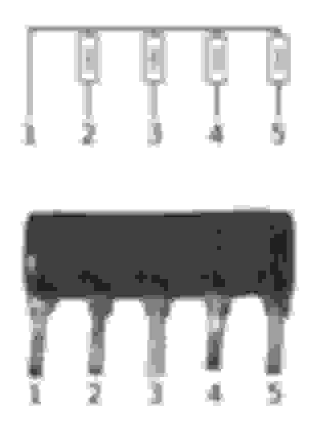
I researched another component, the Resistor Array RA2. I removed RA2 from the circuit and measured the device with a DMM. The Resistor Array is technically a bussed resistor network. Pin 1 is just a wire and each subsequent pin (Pins 2 - 5) has a 10kΩ resistor. The photo below shows both the actual component along with a schematic above it.
RA2: Note the resistors on Pins 2 thru 5.
I checked DigiKey for an appropriate substitute and found 2 components that closely match the physical dimensions and the electrical characteristics. I also attached the datasheets for these 2 substitutes for the Resistor Array. Please note, that the majority of Speedo Boards only has 1 array, RA2 installed. I heard of some that have both installed but have not seen an example board with RA1 installed.
Much like Post 68, Here is a partial update to the master parts list:
is there a replacement for the speedometer motor that drives the needle ? after i removed the needle for other face plates the motor is slower in movement but still accurate after driving a while at the same speed.
I have not seen a suitable replacement for the speedometer motor. It is a stepper motor type and an online search has not yielded positive results.
The stamping on the motor is as follows:
Line 1: 91/12/06 (YY/MM/DD Date Code)
Line 2: S-HR0100
If you find a suitable replacement then please post your finding here! In the meantime, you may have to scavenge a motor from another speedometer faceplate. It should be relatively easy to get considering other members swap out a KPH face for a MPH face or vice versa. It sounds like you have a 2nd faceplate so you could remove the motor from it then install the motor on the desired faceplate. Best of luck on your search for a replacement stepper motor!
problem i think that i have is i have a 300 km/h speedo meter so dont know if it is the same stepper motor as an 180 km/h.
dont have a spare to test this
if i would know that the stepper motor is the same on all of them. then i can easy fix it with buying an other one to use it as donor
What is the part number stamped on your stepper motors to the 300 KPH and 180 KPH faceplates? I suspect that the motor part numbers may be interchangeable. As mentioned above, the USDM 180 MPH speedometer uses the S-HR0100 motor. When converting MPH to KPH, the 180 MPH value equals 289.7 KPH. So I would suggest using the USDM stepper motor on a 300 KPH faceplate.
FWIW, the part number stamped on the Tachometer motor is A-HR0100. There are physical differences between the quantity of pins and their orientation of the Tachometer motor when compared to the Speedometer motor.
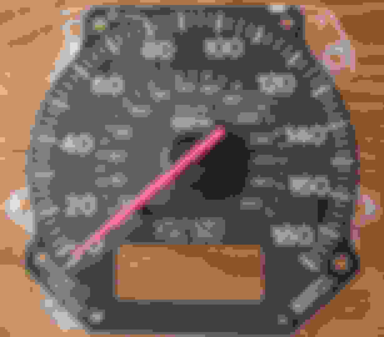
Here are 2 photos showing a USDM 180 MPH speedometer face along with the part number stenciled on its stepper motor. The likelihood of stepper motor failure is rare but possible when removing the speedometer needle. If the needle is damaged (it is easily done) then the motor must be replaced.
There is a how-to thread that discusses removal of the Tachometer needle. The procedures to remove the speedometer needle should be identical to the tachometer. Refer to this thread: Rev Counter Going Crazy Post #2. Then follow the instructions in the attached file titled, "Tachometer Repair.pdf".
i dont know part number as it is still in the car. but i will try with the 180 mph part and swap it
then i just need to adjust it a little with the screw on the side
thanks for the info


 )
)