
Electronic Boost Controller Comparison Chart


Just curious. Whos using the AEM TRUBOOST ?????
I am running one currently, replaced my HKS EVCEZ which was great when I was running the twins, but sucked w/single turbo setup. Anyway, I was hopin some
fellas who were using the AEM TRUBOOST could give some opinions as well as:
1. How MAC VALVE ports ( 1,2, & 3) are routed.
2. Only one vacum line to open wastegate only, or 2 lines (open & shut).
3. Spring opening psi.
4. Duty cycle, what %.
Not to sound stupid, but I want to throw this in. Would most say they have normal amount of backpressure in exhaust manifold or more than average
Sorry I don't have much to contribute.
I've used an AVC-R in the past. Looks cool, but I could never get that damn thing to work right. Always had spikes, it was just messy. I've had many apex-i products and I've always been dissapointed with them =/
I just dropped in a solenoid for my AEM EMS and used the internal boost control options and it runs rock steady.
I just dropped in a solenoid for my AEM EMS and used the internal boost control options and it runs rock steady.
currently just running the basic setup, open loop, duty table, I did notice a slight fluctuation after writing my last post, so I'll be looking at the more advanced options later.
The other one
Joined: Aug 2009
Posts: 263
Likes: 1
From: Cols., OH
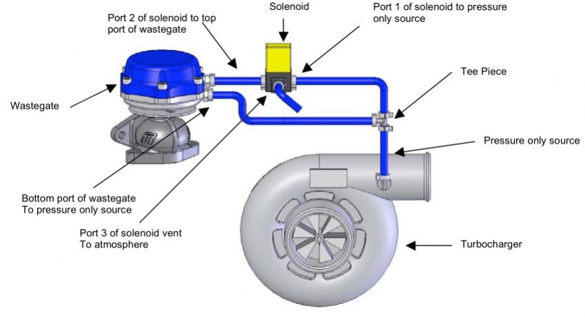
[QUOTE=arghx;10631821]Most everyone is going to to T off the pressure line for the bottom port of the wastegate, and use the solenoid to feed the top port of the gate. That's how the instructions tell you to hook it up. However, you can control an external gate by hooking the solenoid up to the side port only. Spring opening psi and duty cycle vary greatly with each car because it depends on the restriction in the exhaust, the turbo you are running, and the kind of boost curve you are looking for.
In the exhaust manifold? On a single turbo setup? That depends on the setup.
Ok then, I got a gt36r dual bearings of course. AEM TRUBOOST w/port 3 running to port c on my gate. Wait a minute. Oh no, I think I just thought of the problem.
I changed my lines the other day after tigin up some new alum air pipe and I hooked the mac valve up wrong. I got mac ports 1-vent, 2-boost source , and 3-waste gate port c. I will swap 2 & 3 right now.
And my exhaust is 3"dp/3"mp/3" and right to 4.5" straight thru bro. Also I ported my engine for lower rpm torque which works out nice for me on the streets.
On another note. Last night I made a SST which basically is a high grade regulator/manifold/air trap assy w/liquid filled 30 psi guage and bleeder. I got under the car and watched the valve in my gate, it barely cracks open at 2-3psi and is open pretty good by 10psi . Is that normal, I mean I dont want that thing openin that easy do I? I'm goin out now and replumb the mac then redue my test and plat w/the preload too.
Thanks dude
In the exhaust manifold? On a single turbo setup? That depends on the setup.
Ok then, I got a gt36r dual bearings of course. AEM TRUBOOST w/port 3 running to port c on my gate. Wait a minute. Oh no, I think I just thought of the problem.
I changed my lines the other day after tigin up some new alum air pipe and I hooked the mac valve up wrong. I got mac ports 1-vent, 2-boost source
, and 3-waste gate port c. I will swap 2 & 3 right now. And my exhaust is 3"dp/3"mp/3" and right to 4.5" straight thru bro. Also I ported my engine for lower rpm torque which works out nice for me on the streets.
On another note. Last night I made a SST which basically is a high grade regulator/manifold/air trap assy w/liquid filled 30 psi guage and bleeder. I got under the car and watched the valve in my gate, it barely cracks open at 2-3psi and is open pretty good by 10psi
. Is that normal, I mean I dont want that thing openin that easy do I? I'm goin out now and replumb the mac then redue my test and plat w/the preload too.Thanks dude
The longer answer is that AEM is horrible about having a bunch of options, tables, and maps but not explaining the whole architecture of a system in their EMS. There are four parts to the AEM Boost Control system:
Baseline Duty Cycle: You have the Boost WG base duty map which is simple and all you need for open loop control. It sets a solenoid duty % versus rpm and load (manifold pressure in this case but MAF is possible on other applications). In open loop control you just fiddle with the numbers here and the solenoid will be pulsed according to this table. In closed loop control this will be the initial look up table. The EMS will start with whatever duty cycle is in this table and modify the duty cycle according to the trims and feedback method.
Targeting Method: When you go closed loop Boost you have to pick a method of targeting the boost. There are vehicle speed, rpm/throttle, and Hi/low boost switch choices. You can't use the rpm/throttle map at the same time as the other choices.
Feedback method: After you set up your boost targets you have to decide how you want to control boost. There is traditional Proportional + Integral control that the OEM's have been using forever. AEM's implementation of this isn't nearly as precise as some other boost control systems I have used. It's kind of hard to explain P+I (or its sibling, PID) control briefly. If you don't have a solid understanding of the theory behind PID control don't use the P+I in the AEM.
The other feedback method is the boost error duty table. This is probably closer to what you find on external controllers with Feedback settings. The table gives authority to modify the duty cycle output based on the difference between the target boost and the current measured boost. So you can tell it how much duty cycle it is allowed to add when under boosting and how much duty to subtract when overboosting. Like any other feedback system, if these values aren't set right you could get oscillation or spiking. The better you have your base duty cycle table set up, the more effective the feedback will be.
Technically you can use both methods at the same time but that will probably make your boost controller behave worse long before you can get it to behave better.
Trims tables: These are offsets to the duty cycle. I think they are added in after looking up the base duty cycle value but before the feedback calculation, but I'm not 100% on that. The Boost WG INP Duty Cycle allows you to add duty cycle at high altitudes (which have lower barometric pressure). The boost target comp table is a quick way to add or subtract duty based on the target boost.
One more thing: the check boxes are so stupid in this thing. To turn the boost control solenoid on, you have to check the Boost W/G Output box. Then to enable closed loop feedback of any kind you have to select Boost WG Feedback box which can be found in any of the Options menus items for the boost targeting, like Options --> HI/Lo Boost switch. Then you have to check whatever box for the targeting method you plan on using. To turn on the Boost Error Duty table you have to check a separate box for that (Boost FB on Error box) and to use P+I control you have to check a box for that.
So for example if I want closed loop control with the boost error table and the vehicle speed target table, I have 4 frickin boxes to check: Boost W/G Output, Boost WG Feedback, Boost FB VSS, and Boost FB On Error.
So here's an example base duty cycle map, which is something you have already been dealing with:
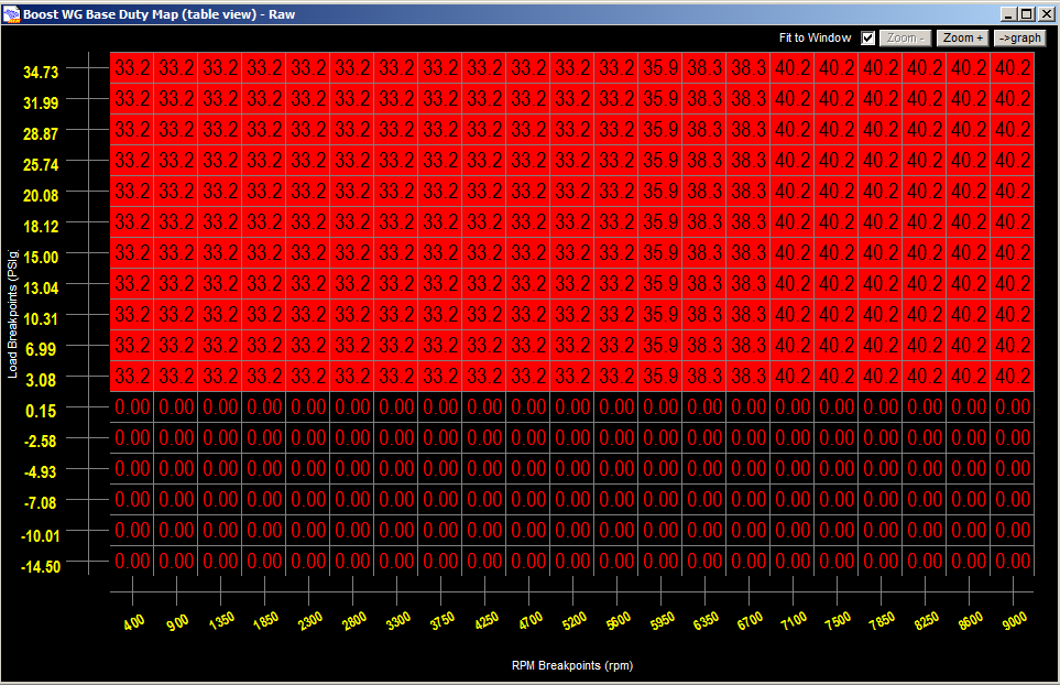
Now if I wanted to reduce wheelspin in 1st gear I could use vehicle speed boost targets and boost compensation tables to drop the duty cycle down. Technically you could still keep it in open loop and use this. To achieve my boost targets using feedback I set authority to add and subtract duty with the Boost error duty table. If this table is set to 0 then the actual closed loop feedback won't do anything (assuming you also have P+I off).

Note that these are just example numbers. In this hypothetical example I gave more authority to drop duty cycle than to raise it; that's just one way of doing things. The duty cycle values in these various tables could vary greatly from engine to engine. As a general comment, these advanced features of the AEM are obviously not for dilettantes; you really have to spend some time learning how they work and spend time tuning hands-on to get them set up right.
Now if I wanted to reduce wheelspin in 1st gear I could use vehicle speed boost targets and boost compensation tables to drop the duty cycle down. Technically you could still keep it in open loop and use this. To achieve my boost targets using feedback I set authority to add and subtract duty with the Boost error duty table. If this table is set to 0 then the actual closed loop feedback won't do anything (assuming you also have P+I off).
Note that these are just example numbers. In this hypothetical example I gave more authority to drop duty cycle than to raise it; that's just one way of doing things. The duty cycle values in these various tables could vary greatly from engine to engine. As a general comment, these advanced features of the AEM are obviously not for dilettantes; you really have to spend some time learning how they work and spend time tuning hands-on to get them set up right.
For a single turbo setup, most instructions for external electronic boost controllers will tell you to connect a T piece coming off the compressor housing. From the T piece, one hose will go to the solenoid and one will go to the side port of the wastegate.
(Turbosmart E-boost2 Instructions)
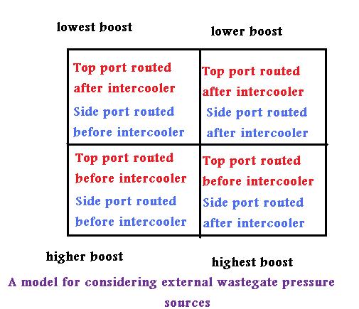
Others suggest you install the T with a pressure source from after the intercooler, because the pressure drop from the intercooler can reduce spiking in this configuration. There's really no "rule" saying that you have to use a T and source pressure from the same place. There are a number of configurations you can use to get a different pneumatic response.
An external wastegate usually has a top port connected to an upper chamber and a bottom/side port connected to a bottom chamber. The gate works on a pressure difference between the top and bottom chambers. Air pressure to the bottom chamber works against spring pressure to open the valve. Air pressure to the top chamber (as regulated by the solenoid) works with the spring pressure to keep the valve shut.
Here are the basic rules:
-- For a hose running to the bottom/side of an external gate, the closer the source is to the compressor housing the earlier the wastegate will open.
-- For a hose running to the top of an external gate, the closer the source is to the compressor housing the later the wastegate will open.
With all that in mind, you have a number of options for setting up the hoses for your boost controller based on your application. A hose to the top port is connected through the solenoid; a hose to the side port goes directly to the gate.
(Turbosmart E-boost2 Instructions)
Others suggest you install the T with a pressure source from after the intercooler, because the pressure drop from the intercooler can reduce spiking in this configuration. There's really no "rule" saying that you have to use a T and source pressure from the same place. There are a number of configurations you can use to get a different pneumatic response.
An external wastegate usually has a top port connected to an upper chamber and a bottom/side port connected to a bottom chamber. The gate works on a pressure difference between the top and bottom chambers. Air pressure to the bottom chamber works against spring pressure to open the valve. Air pressure to the top chamber (as regulated by the solenoid) works with the spring pressure to keep the valve shut.
Here are the basic rules:
-- For a hose running to the bottom/side of an external gate, the closer the source is to the compressor housing the earlier the wastegate will open.
-- For a hose running to the top of an external gate, the closer the source is to the compressor housing the later the wastegate will open.
With all that in mind, you have a number of options for setting up the hoses for your boost controller based on your application. A hose to the top port is connected through the solenoid; a hose to the side port goes directly to the gate.
I'm thinking about trying something, here goes.
Use both a hallman ceramic ball manual AND the PFC boost control.
Why? to be able to control wastegate opening pressure with the manual and max boost with the electronic.
Why again? I keep seeing information stating that manuals tend to hold the gate closed better thus improving boost response / reducing lag
Since the PFC doesn't have a setting for gate opening pressure I figure instead of starting to bleed exhaust too early and affecting spool I can set the manual to say a couple psi lower than the electronic limit and improve the boost curve.
Make any sense at all?
Interesting thread but they use it inversely of what I'm thinking. They use the ebc to control boost ramp up and lower boost levels while the manual controls the maximum boost.
If they set their ebc duty to 0% they get wastegate spring pressure, when they set it to 100% they get MBC pressure. This helps with safety and controlling spikes.
What I'm thinking is cut off the boost signal from the external wastegate side port with the manual and set a minimum pressure with it as to improve boost ramp up so 0% EBC duty will give me Manual controller pressure. Then the max pressure would be setup with the EBC, in my case the PFC.
My reasoning is that normally, depending on boost controller, in order to not overshoot a boost level it cracks the wg open earlier affecting response and I dont want this.
I understand. You want the ability to regulate pressure entering the side and top port independently in the hopes that it will maximizes the response of the gate.
My concern is that manual boost controllers are notorious for fluctuation with the weather and other mechanical issues due to the fact that it is a ball and spring. And a manual boost controller of the ball-and-spring type still has a somewhat progressive opening depending on the mechanical characteristics of the spring and other such stuff. I'm concerned you'll have a lot of variability and instability over time, as conditions change.
Have you thought about just buying a bunch of carb jets and using them as restricter pills to the side port of the gate instead of an MBC? I feel like you would have less variables that way.
Also, remember that hooking the solenoid to the top port gives you a greater ability to force the wastegate completely shut because it pushes down on the valve. It sounds to me that you just need a more precise boost controller. The only external controller that can really do that is an AVC-R, by setting the "start duty." If you had an AEM EMS or other standalone you would also get the flexibility you are looking for.
Go ahead and give your idea shot though. You might be able to tweak it to do what you are looking for.
Yeah, I like the simplicity of using the PFC to control boost with the fog light switch used to toggle the two boost levels. I'd just use the manual to set a min boost, say 12psi and the the PFC do the rest. I'd get a high quality manual with ceramic ball and heavy spring like the Hallman or Perrin. I'm also trying to save a little $.
In PR the ambient temps are fairly constant through the year, the biggest variance coming from driving during the day or at night so I'm not worried about that.
This is a long term idea, I currently can't do anything because I'm daily driving the FD since my dd broke down.
In PR the ambient temps are fairly constant through the year, the biggest variance coming from driving during the day or at night so I'm not worried about that.
This is a long term idea, I currently can't do anything because I'm daily driving the FD since my dd broke down.
I have been asked about the Turbosmart E-boost Street.
I downloaded the manual and it just looks like a less expensive version of the E-boost 2 (see bottom of chart on first page) in terms of the display etc. The functionality is mostly the same in terms of the way you program it and it even has some of the little features like the rpm-based correction.
I downloaded the manual and it just looks like a less expensive version of the E-boost 2 (see bottom of chart on first page) in terms of the display etc. The functionality is mostly the same in terms of the way you program it and it even has some of the little features like the rpm-based correction.
Thank you sir, I appreciate it

great thread I had skimmed through this a couple months ago , but finally got a chance to really read it and try to take it in But I have a couple questions . reguarding the stock sequential twins , and power FC boost controller
in post #18 you were reffering to if someone wanted to change the solenoids to an aftermarket or different solenoid correct?
So me with my stock twins ( JDM ) so no emissions stuff just need to plug the harness into the power FC and I can adjust the boost controller without additional harness splicing of any kind LOL lol sorry I'm just making sure I understood correctly
in post #18 you were reffering to if someone wanted to change the solenoids to an aftermarket or different solenoid correct?
So me with my stock twins ( JDM ) so no emissions stuff just need to plug the harness into the power FC and I can adjust the boost controller without additional harness splicing of any kind LOL
lol sorry I'm just making sure I understood correctly
Last edited by Tem120; Jan 27, 2012 at 09:48 PM.

Yes, killer information!
I have been using a MBC on my single setup for awhile. It works great, and is rock solid. Building my setup strictly for "great numbers with fast spool", I find myself looking into a EBC. I am liking the idea of using the PFC.... I will search further.
I have been using a MBC on my single setup for awhile. It works great, and is rock solid. Building my setup strictly for "great numbers with fast spool", I find myself looking into a EBC. I am liking the idea of using the PFC.... I will search further.
^^ see this thread https://www.rx7club.com/3rd-generation-specific-1993-2002-16/testing-mac-vs-oe-solenoid-valves-other-boost-control-strategies-874031/
the electrical connector you need is at http://www.bmotorsports.com/shop/pro...oducts_id/1674
the electrical connector you need is at http://www.bmotorsports.com/shop/pro...oducts_id/1674
Thanks!
I removed the solenoid control wires when did my single harness. I guess I didn't think of this. I'll be pulling the engine eventually for a port and rebuild. It shouldn't be too bad to pin them back up.
I removed the solenoid control wires when did my single harness. I guess I didn't think of this. I'll be pulling the engine eventually for a port and rebuild. It shouldn't be too bad to pin them back up.

