When you click on links to various merchants on this site and make a purchase, this can result in this site earning a commission. Affiliate programs and affiliations include, but are not limited to, the eBay Partner Network.
Blk 93: i still havent done it, i do plan to, but if i go get my alternator checked. Would that give me a clue as to whether
charge system is fine and didnt get reversed?
Now that you mention it. When i decide to throw the battery back in. Ill monitor the voltage
i will check references. My ECU looks untouched, but it wont hurt to check
Gen2n3: i do have a multi meter
and your explination and diagram makes sense( very helpful)
But ust for my sake as i may not have understood one part
Do i test these with the battery and ECU in their propper place? Sorry this is me double checking
Thanks for the help. Clearly electrical is not my forte
You're welcome for the schematic. Good to know that you have a DMM. It looks like your electrical skills will improve after this task is done!
You have a good question:
Q. Do I test these with the battery and ECU in their proper place?
A. No and Yes. When measuring resistance, it is a recommended for safety to disconnect the battery's negative lead. This prevents damage to the car and avoids electrical shocks to the user should he find a live circuit. When you check the charging circuit you may have probes near the starter and alternator connectors. These draw heavy current and would shock the crap out of you with a misplaced probe. So please ensure the battery is either disconnected from the circuit or removed from the car.
The ECU could be installed in the car however, when measuring resistance of the wires to the ECU then it should be disconnected from the harness. Alternately, removing the ECU may offer better access to its connectors therefore, the discretion to remove it would be up to you.
if i go get my alternator checked. Would that give me a clue as to whether
charge system is fine
Most alternator rebuild shops have a test fixture to determine if your alternator charges or not, and they usually test them for free or for a small fee. It would save you a lot of engine idle time to determine if your alternator is still charging your battery correctly.
You have to be careful about setting correct belt tension when reinstalling alternator, too tight can damage bearings of rotating assemblies.
A non charging alternator isn't your biggest concern however. At worst it could require charging your battery to get you back home if a dash charging light doesn't come on first.
I think swapping your engine ECU is the most important thing you could do, assuming you turned on your ignition switch while jumper cables were reversed, and then nothing happened other than the burning smell. The fact that the car idles isn't an indicator that all is good.
Caps didn't look great, and a visual inspection alone is far from being a good indicator of ECU health to begin with, so I wouldn't trust it until you know voltages for all ECU functions are within tolerances.
It would be far easier + safer and possibly less costly down the road, to buy a used ECU from a trusted source, for the time being. I don't think your wiring is an issue if no fuses were blown.
T�ner: i only checked the pop ups before completely disconnecting the battery
the smell is currently gone ive been smelling every connector i can find. Ill be double checking tho
check the switches on your dash, not the actual pop ups
Blk 93: Hmm i see what you mean
I did want to at some point want to switch to PFC, didnt thinki it might have to bee sooner than later
BUT i will Check to see if the ecu is within tolerance and hopefully its good till my future plan to do a complete overhaul of the car
As for checking the ecu i tried searching for a thread on it but couldnt really find something.
do youhave a link or a process?
Tuner: I just checked function by pressing the button that brings them up
but ill take a look at the dash since its out
Blk 93 suggests that you get a used stock ECU, install it, then test the overall function of the engine. After the new ECU confirms your engine runs to spec then install the original one and make a comparison. The new ECU serves as an insurance policy for your engine. As I recall, the parts fiche has multiple options for ECUs that depends upon trans type, model year, etc... You may need to confirm the part number listed on the parts fiche matches the one from your ECU.
IMO, now would not be a good time to upgrade your ECU because you are trying to find/fix or verify your car's wiring harnesses. Adding a new ECU that requires some modifications would add a layer of complexity to a currently complex problem. It sounds like your confidence is low right now. Believe me, your confidence will increase after you solve this problem! Reading wires is a simple task but it is a tedious process. Your perseverance to fix this problem will pay off!
ok i see what he means
but what if i cant find anything before getting another ecu, should i just go ahead and put everthything back
and start the car with a different ecu?
also i did a resistance test on the ecu connectors and I've marked those that gave me results with a red dot
those that didnt with an x and empty box if there wasnt a wire
Now since this is a first, i dont know how to analyze or process the information i gathered
the ones that i did get results from some varied and some were consistant
(I've only ever checked to see if injectors were firing on an fc ecu wich i used an LED for)
Got my alternator tested and it passed. its good
of course this doesnt mean im out of the woods, but its a small victory and one less thing to worry about.
Last edited by rattlehead; Mar 2, 2019 at 10:42 PM.
You are following similar steps that a doctor takes when diagnosing a patient's problem. Your process of elimination removes any doubt that each component, like your alternator, is good.
Regarding the ECU, that is an answer that only you can make. We offer advise based upon observation and a member's input. It is up to you to take that advise or not. Is your ECU good? Probably, but are you willing to risk testing it without testing other things first?
I have 2 questions about your resistance checks with the ECU connectors:
1. What results did you get - short, open, or some measurement in between?
2. Did you disconnect the connectors at the opposite ends of the harness then ground the pin under test?
The dots, x's, and squares do not provide adequate information for us to help you. It sounds like you measured resistance through various sensors. If you follow the recommendation and example schematic for testing wires then you should only measure a short (0 Ohms) or an open (O/L or OL).
Additionally, you should be looking for shorts where they should not be. For this reason, you must compare the rest of the wires to the 1 wire under test. It is VERY handy to have a copy of the schematic and a sheet of paper near to research or record anything unusual. Don't stop testing wires should you find a problem. Test & record everything first. After all the wires were tested then verify the bad measurements to ensure that is actually the problem. Like the old saying goes, measure twice then cut once. Follow this advice to avoid falling into a rabbit hole; trust me...it is easy to do when reading wires!
Some other pointers to follow: read the front matter in the Wiring Diagram Manual (WDM). It will help you understand all the schematic symbols, color codes, harness locations, etc... Make sure to check all branches of a wire. This is commonly overlooked and easily mistaken for a problem. If the schematic has a tie point on a given wire then that creates an additional path, aka branch, and must be checked. Think of it like a T intersection on a one-way street. Normally, a car could go in 2 directions: left or right. Does that make sense?
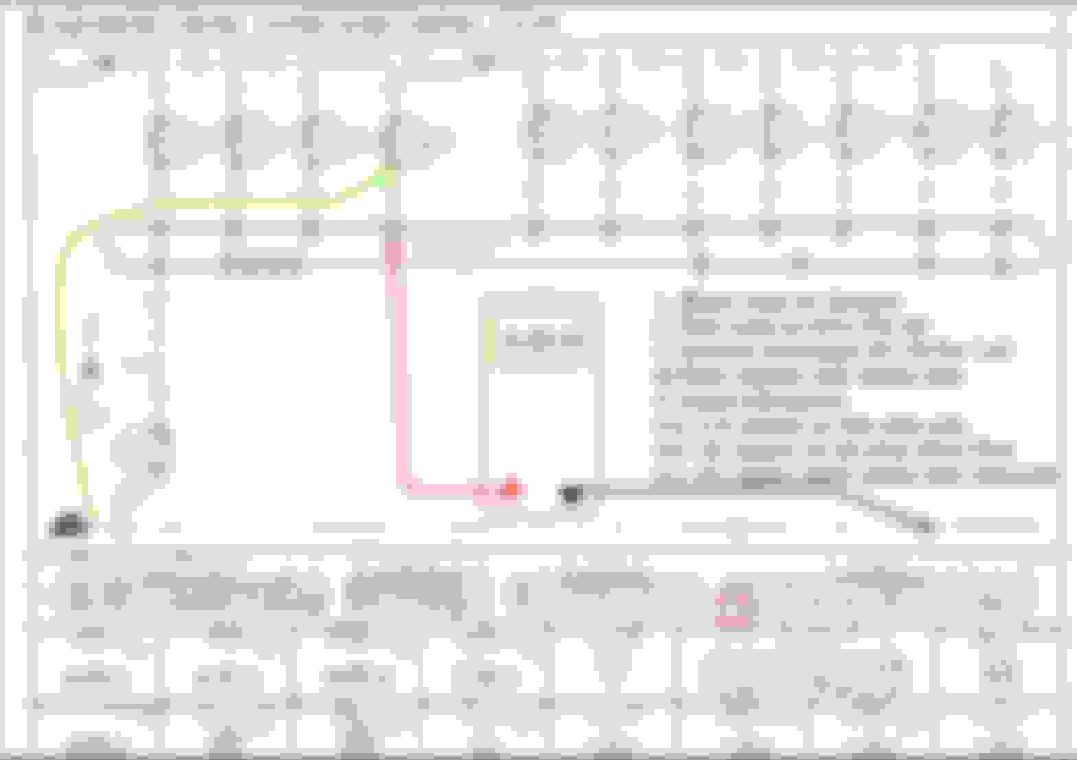
Here is a good example:
Diagram B-1b, WDM
You want to test the wiring from the ECU at Pin 2B. It has 3 possible branches. First, it goes to the Datalink Connector at Output 20 (Pin "IG -", refer to Diagram U for specific location). Second, the wire goes to the Instrument Cluster at Output 18 (Connector 3F on the Instrument Cluster, See Diagram C-1a). Third, if equipped, the wire goes to the ECU for the A/T section (refer to Diagram H-1). We will consider this example as a M/T car.
To properly test this wire it requires:
1. Short the Datalink IG - (negative) pin to chassis ground by adding a wire.
2. Disconnect Connector 3 from Instrument Cluster.
3. Connect the DMM black lead to chassis ground next to the ECU location.
4. Connect the DMM red lead to Pin 2B.
The result should read a short at Pin 2B. You also need to check Pin 3F on the Instrument Cluster connector; it too should read a short. Test the remaining wires around the ECU - all should read open, except for wires that are connected to chassis ground.
Next, disconnect the wire from Datalink connector then re-test. The result should be open, which is a good indication. Overall, this configuration passed the test because parallel paths checked good.
Now, if you skipped Step 2, aka did not remove the instrument cluster, then attempt to measure resistance between the ECU at Pin 2B to Datalink Pin IG - (negative) then it may mislead you.
Hypothetically, the result reads 2 kOhms at Pin 2B. It is not a short, which is bad.
Next, disconnect the wire from the Datalink connector then re-test. You are testing for an open circuit which is a good indication.
Hypothetically, the result reads 2 kOhms at Pin 2B. It is not an open, which is bad
If you are unaware that the Instrument Cluster must be disconnected prior to testing this wire then it may give you a false indication that a problem exists in this wire. When the instrument cluster is connected, the DMM measures the parallel path to ground through the instrument cluster. Do you see the difference?
let me appologise in advance if it seems like were going in circles here due to my lack of understanding the subject
answering your questions
1. When checking ECU harness connectors, i got different types of results-
- 0L on my diagram I put x which i should have explained
the next were marked with a red dot
- some were very specific 00.0, 00.2-3 ohms, 0.22 k ohms, 1.2 k ohms
-and some started at as low as 3 M ohms or 15.5 M ohms and would fluctuate and never really stop * interpretting the data is were im lost, or probably not understanding it at the moment2. I dont know if i did. i do know that i have my cluster and climate controls disconnected
its possible i could have been testing completely wrong
i have not disconneced anyting on the other end of the harness that goes to the engine
this is basically what i did, this is what i understood from the previous post.
Im gonna have to keep reading the second half of you respond many time to try and figure out how that process goes
because its honestly not making sense to me.. yet
Thank you for explaining your test methods. The measurements of .22 kOhms and above mean that you are reading through sensors or other resistor networks. My recommendation would be to disconnect the other side connectors. That would remove the sensors etc from the wire harness. Then follow my advice from Post 25 by grounding 1 wire (on the opposite end) to the chassis.
-i am purposely creating a short by grounding the wire(tells me that the wire is complete from start to finish, this gives me a reading of 0.__ ohms)
-i check to see if the remainder of the pins in connector remain OL which is the desired outcome
-if i get a reading from another then that means those 2 wires are on the same path(sheathing is melted and wires are touching)
Im currently trying to learn how to better read Wiring diagrams and then be able to locate what im lookin for on the car,
which i think will be a big help and cut a lot of guessing and wasted time
Last edited by rattlehead; Mar 3, 2019 at 10:56 PM.
Not to confuse you, but if you do see a short on other pins then there is a chance those other pins are connected to ground (or wasn't disconnected). If everything was disconnected and you are reading a short then that other wire is touching the current wire under test.
As an example, if you read a short at ECU Pins 4A, 4B, 4C, and 4D when checking ECU Pin 4Z then that is also a good indication because Pins 4A, 4B, 4C, and 4D are Ground. If these 4 pins read open then that would be a problem. This assumption is only valid while the wire under test is grounded to the chassis.
You should also see opens on ECU Pins 1P, 1V, 2A, 2C, 2D, 2E, 2F, 2G, and 2H unless you have an auto trans or a Canadian option. The schematic shows these pins with an "*" (asterisk) and may have a wire color code in parentheses below it. These 9 pins should not have a wire connected to its slot; unless your car has an auto trans or is Canadian.
BTW, I use a 94 WDM which applies to the 94-95 FD. There are minor differences in wiring between a 93 and 94. Please make sure you use the correct reference.
If you want to learn more about reading schematics then I recommend reading the front matter of the WDM (mentioned earlier) and use some google-fu skills. Does that help?
Ok this is becoming much more understandble and also doable!
some clarification, some of my old readings never stopped or settled and that was due to the otherside being connected, correct?
for the possible confusion you mentioned,
1. if a wire is already properly grounded it should be 0.__ ohms correct?
2. if it is grounded but is also touching the currently tested cable it should read much more, correct? unless ther is an exception to this part?
The next biggest thing would be translating the diagram into the physical thing since car isnt laid out as simple.
thanks for helping me understand things this far!
Correct. You're checking the continuity between two points, if there is no resistance (or it is negligible like < 200 Ohm) then continuity is confirmed.
Thank you for the assist in answering rattlehead's question.
rattlehead,
Be careful when asking about a properly grounded wire. Are you asking what is a typical resistance measurement for a piece of wire?
Ideally, the answer is 0 ohms. Realistically, anything under 2 ohms is a short. When working on my FD, I typically see 0.6 ohms or less. Many factors such as length of cable, number of connectors, age of wire, and types of metal will cause resistance measurements to fluctuate a bit.
Not trying to argue Arman's talking point here but there is difference between measuring resistance and verifying continuity in wires. When checking for continuity, the DMM tests for a complete path for current to flow. It will give an audible tone and should display a resistance value. You can learn more about it here: Fluke: What is Continuity On older DMMs, the continuity function doubled up with a diode function and displayed something different. That goes beyond the scope of our conversation for now. The convenience and popularity of the continuity check is the audible tone which allows you to quickly sort through a bundle of wires without looking at the meter. Once you hear a *beep* you can move on to the next wire.
Based upon my experiences with different DMMs, most had the continuity function doubled with the diode function. The preference between continuity or resistance checks depends upon the DMM and what is the result. If a test calls for a specific resistance, say 100 ohms then use the resistance function. If you are going to spend time with your head turned upside down in a footwell with poor lighting and confined space then chances are hearing a beep vice attempting to read a digital display may suit your needs.
To answer your 2nd question, if 1 wire is grounded and a second wire touches the 1st then the resistance will be 0 ohms. Generally speaking, electricity will travel to ground via the path of least resistance. For example, 1 wire goes to a primary injector and a 2nd wire goes to ground. If the primary [fuel] injector wire touches the ground wire then the primary injector shuts off because current no longer flows to the injector. It was diverted to ground. It doesn't matter if they touch right at the injector or close to the ECU because the current found a faster path to ground.
Think of paths to ground like traveling down the highway. What happens when you have a slow driver in front of you? You get around the slow driver then resume your original speed. Now what happens when you drive down a 1-lane road and encounter a slow driver? You have no choice but to drive as fast as the slowest driver. Electricity works in a similar fashion. The road is the wire, the car is an electron, and the speed at which the car travels depends upon traffic conditions, similar to current flow in an electrical circuit. Makes sense?
To start, I guess "properly grounded" is probably not the best term to use
i guess i was thinking it was meant to already be grounded
but i could be wrong either way
based on armans response it makes sense and puts my readings of 7Mohms into some perspective
My DMM does have a beep for continuity so ill try that again
Also Good analogy
After doing research and looking at diagrams and the thread with all wire harness connectors labled, i think ill be able to go and get better desired results now that im able to understand the "map"
Also if you know off the op of your head what the gauge of wire goes to the alternator connector for w/g & w/b cables?
I finally got some free time to work on the FD
Lucky or unlucky, i found this
My guess is that while jumper cables were backwards
Setting the key to the on position (normally theres a click from the engine bay, something activating something to do with emissions is my guess considering the yellow plug is for emissions)
could have caused this, and this is what i ended up smelling
Took plastic off and the wire looks normal
I have unplugged every connector on the engine harness
And checked for any shorts. Nothing came up on my DMM unless i purposly grounded it.
I still have one more test to run..
Last edited by rattlehead; Apr 6, 2019 at 06:28 PM.
I merged the Pt2 thread into your original thread.
Thanks for sharing the pic of the melted connectors. Ouch! Despite the connectors tested ok they are physically damaged. IMO, those 2 connectors should be replaced. I would also be wary of the wire flexibility to those connectors and thru the rest of the harness. They could be brittle or have the potential to prematurely breakdown because they were overheated. If the wires appear to be flexible then it may be ok.
Im in the process of deciding whether or not to remove the engine harness and inspect it and re-wrap it.
The cables do appear to flex like normal wires and dont look melted or anything.
Considering that i had already started the car upon initial incident(and it didnt burn down) and my alternator and battery checked out good
I feel confident in the car working well
The fire extinguisher sounds like a good plan to keep a peace of mind. Is it rated to handle Class A, B, and C fires? BTW, a Class C fire is an electrical fire.
What are those 2 melted connectors attached to? If not done already then you may want to double check the wires or connectors along their path. That would ensure nothing else got melted.
You should be able to source replacement connectors for the melted ones. They may not be the same color but you should be able to get the same configuration.
Thanks for the update and please, keep 'em coming!
Today I have done what I have been dreading to do.
start the car.
I put everthing back and got my extinguisher ready
It started and died, then remembered fp resistor
After that The car started and ran like normal. it warmed up
nothing but the sweet smell of exhaust and sound of 13b running
Overall I think I probably got really lucky with this incident
Big thanks to Gen2n3 and those that responded.
Last edited by rattlehead; Apr 27, 2019 at 03:56 PM.