When you click on links to various merchants on this site and make a purchase, this can result in this site earning a commission. Affiliate programs and affiliations include, but are not limited to, the eBay Partner Network.
I am writing to you as I don't find any solution to fix my Climate control (photo reminder below). I did check the forum and I found A LOT of information, but very few information on how to fix CC heater unit. (I may have miss something though..)
I did check the fuse -rear wiper- and all. I arrived to the point where I found out the blowers were working fine, only the controls are not responding.
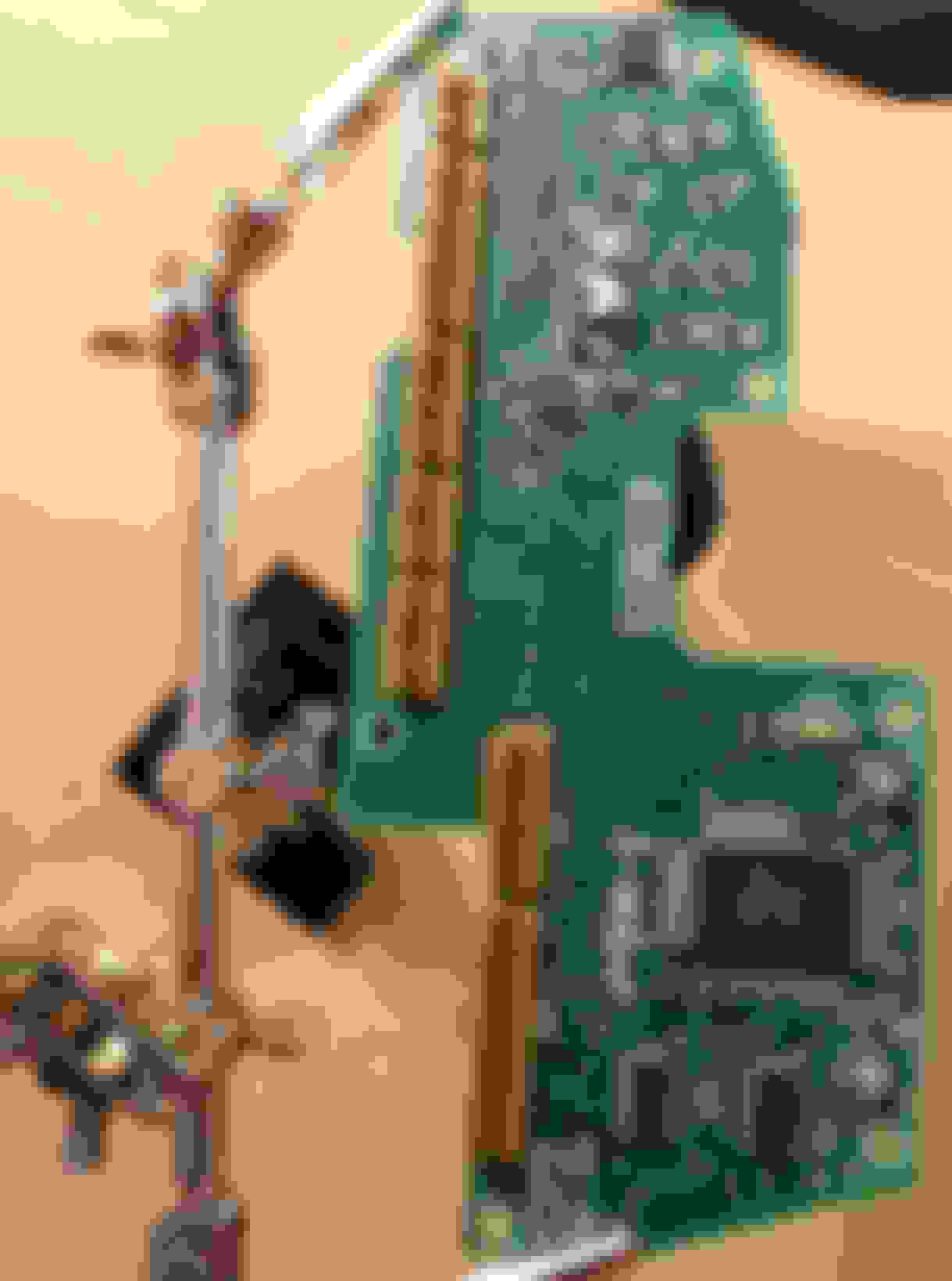
Due to the rarity of this part, I decided to have a look inside.
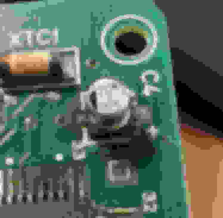
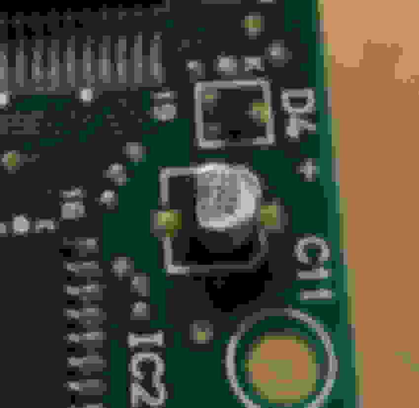
I found out that the board overheated on some areas, and the SMD capacities are gone or bad looking. Literally the C2 capacity disappeared on the board below... No wonder it's not working !
I would like to change the capas, clean the board (not done yet) and see if this could be enough to fix my CC heater unit.
Here is where I need your help :
I am not an expert of electronics, especially in identification of the value of the capacitance.
I have identified 3 different values for the capas with following spec (if you think there are more than 3, please tell me) . 1/ On one of the Capa, I have the following information on the right of the black area (negative polarity marking) :
* (some rectangular drawing) 1m
* 1 0
* 16V
Diameter: 4mm x ~5mm
2/ on the right of the black area (negative polarity marking) :
(some rectangular drawing) 1 m? or L?
R22
50V
Diameter: 4mm x ~5mm
3/ on the right of the black area (negative polarity marking) :
(some rectangular drawing) 1 L? (I can't find out what the letter is, if it's a letter...)
10
50V
Diameter: 6mm x ~5mm
My guess is :
1/ should be 10�F with nominal tension of 16V
2/ should be 0.22�F with nominal tension of 50V
3/ should be 10�F with nominal tension of 50V
What is your guess ? Can someone confirm or teach me how to read these ?
Thanks in advance for your help guys,
Ben
PS: I never post on forums in general, so please be indulgent
Ben,
I cant provide an answer to your problem, unfortunately.
What were the symptoms you were experiencing? I also have a problem with my CC unit, and have not been able to find anyone in the UK who can sort it, hence now looking further afield.
Thanks
Lee
The auto climate control was only on JDM cars and only as an option on certain cars. There's not a lot of knowledge about them unfortunately, especially with regards to troubleshooting problems.
Hopefully someone with some electrical expertise can chime in on this thread!
Lee,
Thanks for your answer. Never mind, so far nobody does .
The symptoms were :
* the fan speed cannot be selected (no light, and no speed change when turning the selector)
* same behavior for the direction of the air (no light to identify in which position it is, no changes if I change through the selector)
* from time to time, the blowers would blow stronger without any changes of the driver. sometime not blowing at all...)
I found some hints on the forum thanks to threads and the JDM workshop (see above), I checked the related fuses (riya-waipa (how lovely): rear wiper and the ones in the engine bay : all goods)
I did some tests on the fans (engine bay), and somehow put the ECU in "test mode" (I guess) as I was able to hear/feel the different speeds of the blowers inside the car.
At that point, I figure out that the issue might come either from the "A/C amp" or from the "Heater control Unit" (see below).
And I then you know the status from my first post. I will order some capas and test if It could change anything...
At least, to be able to control manually the speed of the blowers and the direction, would be great ! Not expecting the auto climate to work in "auto mode" ^^'
Dale,
Thank you for your answer, yep you're right unfortunately... not enough auto climate in the market
Actually a troubleshooting method does exist in Japanese !... but even with go*gle trad I can't clearly go through it; my Japanese skills being really limited.
I can't resist to show you this one below as example (yes, I did some long evening researches in the JDM workshop)
There are plenty, but some of the troubleshooting methods are described with specific tools... that I don't own or understand. ^^'
Anyway, I will keep you posted on this topic. But please don't expect fast answers
In case anyone would be interested in this thread, I will post there how far I am with this issue.
I did a check of the "A/C amp" just in case, and as you can see below... the board is very clean.
So I exclude this part for being the issue. Clean "A/C amp" board
What I did :
I did order some Capas but I did change only 2. (10�F 16v) C2 and C4 on the board (check the first post for location)
the board was damaged for the minus leg of the capas. I had to improvise and scratch the board to find back the original copper track in order to solder.
I did a very bad work there, so you will not see that in picture (I am too ashamed of it) but at least it seems to work !
My plan was to change all the capas, but I did break the minus leg of the board while dismounting the C4.
Plus seeing my "work" make me realized I had to stop the massacre. ^^'
I went to the garage to test and... it fixed the controls !! But not the HMI :
Test condition : +APC (engine not running)
test results :
I can now change the fan speeds ! (never worked before)
I can now change the air direction ! (never worked before)
the stop button finally works ! (never worked before)
I don't have a single light for HMI feedback :
the dim lights are working fine when I switch on the lights but I don't have the indicator/feedback light for the selection (red circles below):
more generally, non of the indicator/feedback lights are working : even the auto button doesn't light but I think it works though... these lights doesn't work
So I don't know if I am in auto mode or not, only guessing...
What remains to be done :
To found a way to get the feedback lights on.. If anyone has a hint. I would greatly appreciate it
After not having the car on the road for a couple of years, and getting it back on the road this year, the CC has developed a mind of its own, switches itself on/off, changes temp, direction, and mode without human input.
Hoping to have a look at the electrics over the winter and see if I can spot any faults.
Let us know if you get the LEDs (feedback) working.
My re-circultation has never worked (for 12yrs of wonership) and the 'AUTO' was tempremental showing green on occasion when 'AUTO' mode was enabled, but that LED stopped working about 10 years ago.
The last time (~8 years ago) I took the PCBs out, I saw nothing visually wrong, gave it all a clean (contanct cleaner) and re-fitted, no change. Next time will look to try and test connectivity/resistance.
In case anyone would be interested in this thread, I will post there how far I am with this issue.
I did a check of the "A/C amp" just in case, and as you can see below... the board is very clean.
So I exclude this part for being the issue. Clean "A/C amp" board
What I did :
I did order some Capas but I did change only 2. (10�F 16v) C2 and C4 on the board (check the first post for location)
the board was damaged for the minus leg of the capas. I had to improvise and scratch the board to find back the original copper track in order to solder.
I did a very bad work there, so you will not see that in picture (I am too ashamed of it) but at least it seems to work !
My plan was to change all the capas, but I did break the minus leg of the board while dismounting the C4.
Plus seeing my "work" make me realized I had to stop the massacre. ^^'
I went to the garage to test and... it fixed the controls !! But not the HMI :
Test condition : +APC (engine not running)
test results :
I can now change the fan speeds ! (never worked before)
I can now change the air direction ! (never worked before)
the stop button finally works ! (never worked before)
I don't have a single light for HMI feedback :
the dim lights are working fine when I switch on the lights but I don't have the indicator/feedback light for the selection (red circles below):
more generally, non of the indicator/feedback lights are working : even the auto button doesn't light but I think it works though... these lights doesn't work
So I don't know if I am in auto mode or not, only guessing...
What remains to be done :
To found a way to get the feedback lights on.. If anyone has a hint. I would greatly appreciate it
I will let you know if I find anything
Ben
Hi Ben,
Very useful write up. Thanks for the effort. I�ve had similar issues for over 10years. Mine started with intermittent CC issues just as you describe, however for the last 5-6 years my whole CC/AC is totally dead. I�ve checked the rear wiper fuse, tried changing relays and I�ve just tried replacing the caps as per your thread.
Still no joy!
Question? Was your system entirely dead
when you pulled the chip board and changed the Caps? Im wondering if there is something more simple that I may have missed that brings back the power connection to the control unit?
I�m now fully restoring my 92 FD to as close as factory as I can. I would love any advice that anyone thinks could help with the CC/AC/blowers. I very much need them in London otherwise I�m wiping the steam off the inside of the windscreen every time it rains (every other day in the UK ha)
This is my first time posting. This place has helped me loads in the past.
Any updates? I have the auto climate control in my FD and mine sometimes won't turn on until the car's been warmed up a bit so I may start digging into this soon. I have some background in electronics but it's been awhile.
Stuff you can do without much investigation:
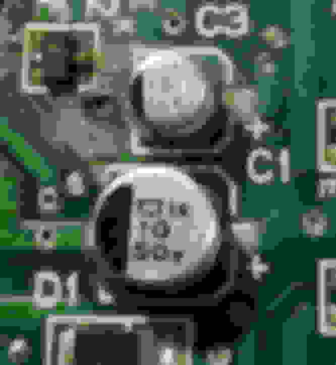
1.) I would start by replacing all of those electrolytic (round) capacitors (you can usually go up in capacitance without harming anything and it will actually improve filtering, so that's something you can try in case the original design used borderline capacitor specs). This is just for reliability reasons and because it's simple. Use ceramic replacements if possible.
2.) Replace all the discrete logic chips (look like this)
No re-programming or anything required. They should have part numbers like 74XX or 4XXX. Just find the same part number and replace it since they're just generic circuits. discrete logic chip
3.) Replace that MOSFET in the top center left and any others I might've missed.
4.) Other ideas: Bake the circuit board (look up baking GPU guides) and/or use an ultrasonic cleaner bath. Baking should reflow all the solder connections and help if there's a broken/marginal connection. Ultrasonic cleaning is fairly risk free as long as you don't run it for more than a couple minutes (I've revived some GPU boards with this method). But since these boards are almost certainly using leaded solder, broken solder joints is probably less common of an issue than in modern RoHS boards so it may not fix anything.
(Warning: If you screw up the baking you can make things worse)
Some investigation / more advanced work potentially needed on this stuff:
1.) Potentially EEPROM or microcontroller chip(s) on the board are bad, but from your symptoms it seems to be saving settings but then going haywire so I don't EEPROM is the issue. Anyway, wapping these should just clear/reset any memory settings and not require programming to work, but since it's an old design you can probably just copy the old EEPROM memory to a new chip with a basic reader and put the new chip in. Think of it like replacing RAM in a computer.
I can't read it, but that square, burnt-out chip with tons of pins looks like a microcontroller that will may not work if you just find a similar part number and copy it. You'd need to copy its program onto a new chip before replacing, otherwise the replacement will basically be a totally different logic chip.
2.) Bad potentiometers / input to the board (the dials themselves)
It's probably less headache to just ship the board off to an electronics repair shop and pay them $100-200 to fix it. The parts themselves are usually really cheap though so I wouldn't be afraid of just replacing everything possible on the board if you feel up for it.
Last edited by sman2600; Sep 22, 2025 at 04:31 AM.
Anyway, I will keep you posted on this topic. But please don't expect fast answers
Ben
The first board looks toast, and what's most worrisome is that it looks like a microcontroller got fried potentially.
Here's some translations for that last image:
Troubleshooting steps with a 60w Lamp (tldr; shine a lamp onto the sensor in the front right of your dash troubleshooting)
Flowchart by Malfunction System Air Conditioner By Malfunction System Malfunction Phenomenon: - During self-diagnosis, service code "02" is displayed
Flow No. Inspection of Solar Radiation Sensor System (Auto Air Conditioner)
Related malfunction parts: - Solar radiation sensor, A/C amplifier, wire harness
Caution: - During self-diagnosis, if the solar radiation sensor is not illuminated by a light such as a lamp, code 02 may be displayed.
A/C Amplifier Brown-black Purple-red
Solar Radiation Sensor
Step 1 Incandescent Lamp
Preparation Illuminate the solar radiation sensor with a 60W lamp from about 10 cm distance.
M 16 Connector G U-28 Solar Radiation Sensor Instrument Panel
Step 2 Inspection of Solar Radiation Sensor 1. Turn the ignition switch OFF. 2. Disconnect the solar radiation sensor connector. 3. Measure the output voltage between the terminals of the solar radiation sensor.
Measured Voltage 0.3~0.5 V
Reconnect the sensor connector and proceed to Step 3 inspection.
Others Replace the solar radiation sensor.
Step 3 Inspection of Harness 1. Disconnect the A/C amplifier connector. 2. Measure the voltage between terminal G (brown-black wire) and terminal M (purple-red wire) of the 16-pin A/C amplifier connector.
Measured Voltage 0.3~0.5 V
Others Replace the A/C amplifier. Repair the harness.
(Note: A/C amplifier solar radiation sensor wires: brown-black, purple-red)
All the "F" suffix boards eventually suffer from this and unfortunately it's the board fitted to the vast majority of climate fd's. What you ideally need is a "J" suffix board from a late climate equipped car. This board was redesigned using a few different components and I'm yet to see one showing issue.
Root cause appears to have been a damaged ceramic capacitor that created a short circuit.
Other issues were: leaking electrolytic capacitors damaged the microcontroller traces (traces had to be cleaned and then repaired with copper wire and the capacitors replaced)
It's been a while since I connected. Regarding my issue, I'm still stuck in the same point, and actually my fix was not 100% ok. Meaning that I still have randomly nothing runing... I'm convinced the capacitors needs to be changed to recover the functionnalities.
@sman2600 Thank you so much for your replies ! It is actually the first time I am having hopes for this topic ! I'm now pretty sure the controller soldering are toasted and I would need to solder again as described in the japanese linked you mentionned ! I would need to check if I also have a ceramic capacitor that is broken... But it will not be soon, as I have other priorities right now. My 7 had an issue with the alternator, introducing higher voltage on the onboard power supply network, now it's fixed but that's potentially the side effect on this heater control. @Ceylon Thanks for this precious information ! This is really appreciated. I will start to hunt this down, I don't think mazda re-produce this "J" part thought.
Honestly you guys provided me great informations : potential root cause with Japanese thread + a method to rebuild the PCB & reliable solution with the "J" Board. (Now it's more how to get this "J" part, my new graal. So I believe I will try to recover the board probably with an electronic expert, which sounds more realistic).
You have all my gratitude, hope these information will help other Auto climate control owners around the world !


 .
.