
Which Vac lines to connect to MAP. Modified S4 N/A

Thread Starter
Rotary Enthusiast
Joined: Aug 2004
Posts: 1,100
Likes: 0
From: The World
Hi Guys,
I'm running a Series 4 13B N/A with the S4 manifolds - but a bit modified. I also run an aftermarket ECU so vacuum is pretty important.
I just want to make sure its hooked up correctly. I will post a few pics of the intake and where current hoses go, and then give you some vac readings I get in different situations, hopefully someone can let me know if it looks right/wrong etc. cheers
Basic vacuum system summary:
A line comes from the LIM off a tube there, joins a T. One pipe runs to the end of the plenum, the other goes to the ECU.
Plenum:
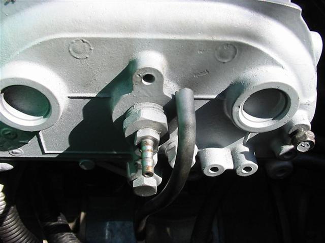
The vac line that connected to LIM runs to the one in this pic, with no hose on it (next to the one with hose on it):
Now for some figures
At idle the map sensor is reporting: 16-17"Hg
Holding steady revs in neutral at 4000rpm: 19"Hg
With some load on the engine, reversing: 12"Hg (trying to load it up as much as poss without stalling)
And during acceleration in neutral: 00"Hg
Any tips would be awesome. I'm just wanting to make sure that I am hooked up to the correct vac lines for my MAP sensor, as I am going to be dyno-tuning AGAIN soon (for the 4th time) and this time want to make some progress!!
Thanks so much,
Paul.
I'm running a Series 4 13B N/A with the S4 manifolds - but a bit modified. I also run an aftermarket ECU so vacuum is pretty important.
I just want to make sure its hooked up correctly. I will post a few pics of the intake and where current hoses go, and then give you some vac readings I get in different situations, hopefully someone can let me know if it looks right/wrong etc.
cheersBasic vacuum system summary:
A line comes from the LIM off a tube there, joins a T. One pipe runs to the end of the plenum, the other goes to the ECU.
Plenum:
The vac line that connected to LIM runs to the one in this pic, with no hose on it (next to the one with hose on it):
Now for some figures
At idle the map sensor is reporting: 16-17"Hg
Holding steady revs in neutral at 4000rpm: 19"Hg
With some load on the engine, reversing: 12"Hg (trying to load it up as much as poss without stalling)
And during acceleration in neutral: 00"Hg
Any tips would be awesome. I'm just wanting to make sure that I am hooked up to the correct vac lines for my MAP sensor, as I am going to be dyno-tuning AGAIN soon (for the 4th time) and this time want to make some progress!!
Thanks so much,
Paul.
Former Moderator. RIP Icemark.
Joined: Apr 2001
Posts: 25,896
Likes: 24
From: Rohnert Park CA
I don't quite get your set up, but the MAP sensor should be hooked up as close to the intake port as possible. Of course I would probably also put in a restrictor insert that blends the pulses.
You would not want to use the DEI/plenum chamber for the Hg reading as you will get a slightly lower reading at higher RPMs due to the DEI effect.
You would not want to use the DEI/plenum chamber for the Hg reading as you will get a slightly lower reading at higher RPMs due to the DEI effect.

Thread Starter
Rotary Enthusiast
Joined: Aug 2004
Posts: 1,100
Likes: 0
From: The World
Originally Posted by n/a-luvr
am I correct in seeing you make less hp and torque than factory s4 specs? ~rich
Originally Posted by Icemark
I don't quite get your set up, but the MAP sensor should be hooked up as close to the intake port as possible. Of course I would probably also put in a restrictor insert that blends the pulses.
You would not want to use the DEI/plenum chamber for the Hg reading as you will get a slightly lower reading at higher RPMs due to the DEI effect.
You would not want to use the DEI/plenum chamber for the Hg reading as you will get a slightly lower reading at higher RPMs due to the DEI effect.
What's the plenum vacuum connection meant to be used for?
And what's this restrictor you talk of?
Thanks!!
PS. Intake came welded... sucks for getting to primary injectors.

HAILERS
Joined: May 2001
Posts: 20,563
Likes: 27
From: FORT WORTH, TEXAS,USA
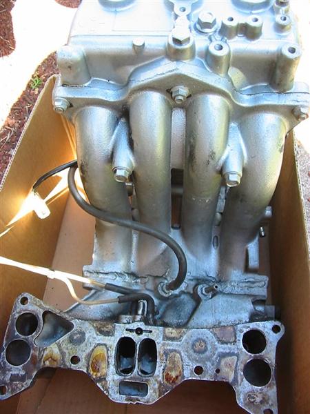
In the bottom picture, where there is one BLACK vacuum line coming off a nipple to the left, BUT a similar nipple sits to its right with nothing on it, either of those nipples is where I'd go for the manifold pressure to the aftermarket ECU and boost/pressure sensor. Those two nipples seem to lead to the primary runners. I came to that conclusion form looking at NZC's Wombat post a few minutes ago.
http://wombat.sevarg.net/RX7/RX-7_Tr...%20Systems.pdf
http://wombat.sevarg.net/RX7/RX-7_Tr...%20Systems.pdf
Thread Starter
Rotary Enthusiast
Joined: Aug 2004
Posts: 1,100
Likes: 0
From: The World
Originally Posted by HAILERS
In the bottom picture, where there is one BLACK vacuum line coming off a nipple to the left, BUT a similar nipple sits to its right with nothing on it, either of those nipples is where I'd go for the manifold pressure to the aftermarket ECU and boost/pressure sensor. Those two nipples seem to lead to the primary runners. I came to that conclusion form looking at NZC's Wombat post a few minutes ago.
http://wombat.sevarg.net/RX7/RX-7_Tr...%20Systems.pdf
http://wombat.sevarg.net/RX7/RX-7_Tr...%20Systems.pdf
I think the connection on the plenum is meant for the Bypass Air Control valve to control idle with an ECU - from that diagram you linked! Interesting. What were they thinking when they built and installed my engine lol.
Cheers!
Trending Topics
Thread Starter
Rotary Enthusiast
Joined: Aug 2004
Posts: 1,100
Likes: 0
From: The World
Hoollld up. Discovering more detail 
Looking at a better diagram now. The plenum connection runs to a 'Pressure regulator control solenoid valve' - which in turn runs to an EGR valve. Dont have one of those.
Does vacuum on the pressure regs adjust the pressure at which they regulate?? This could also complicate things perhaps..
My primary fuel rail is an S4 N/A. It has the fuel pressure reg on the end. The vac hose runs from this and into a T between the LIM nipple and the next T (with the plenum and map sensor) (sorry i left this out earlier - its such a bitch of a setup). I will draw a diagram to make it easier
My secondary fuel rail is S4 Turbo lol! It also has a pressure regulator on it. Dont worry about fuel flow - I have them hosed up in parallel to prevent flow issues.
Secondary fuel rail pressure regulator has a vac line that runs from this to one of the nipples on the inside of the LIM - this is the hose you can see in the pic.
THE COMPLETE PICTURE:

Tips on rerouting?
Looking at a better diagram now. The plenum connection runs to a 'Pressure regulator control solenoid valve' - which in turn runs to an EGR valve. Dont have one of those.
Does vacuum on the pressure regs adjust the pressure at which they regulate?? This could also complicate things perhaps..
My primary fuel rail is an S4 N/A. It has the fuel pressure reg on the end. The vac hose runs from this and into a T between the LIM nipple and the next T (with the plenum and map sensor) (sorry i left this out earlier - its such a bitch of a setup). I will draw a diagram to make it easier
My secondary fuel rail is S4 Turbo lol! It also has a pressure regulator on it. Dont worry about fuel flow - I have them hosed up in parallel to prevent flow issues.
Secondary fuel rail pressure regulator has a vac line that runs from this to one of the nipples on the inside of the LIM - this is the hose you can see in the pic.
THE COMPLETE PICTURE:
Tips on rerouting?
HAILERS
Joined: May 2001
Posts: 20,563
Likes: 27
From: FORT WORTH, TEXAS,USA
That ORANGE line coming from the lwr intake manifold and going to the FPR but also going to the dynamic chamber (plenum)..................I'd remove the line going to the dynamic chamber. It should not be tee'd into the FPR line at all in my honest opinion, much less the ECU. But then again, I'm just a stock person who does not play with aftermarket items so take it for what it's worth.

certified nutz and boltz
Joined: Jan 2006
Posts: 230
Likes: 0
From: myrtle beach, sc
1, Why wouldn't you run both FPR's from the same vacuum fitting?
1a. Why wouldn't you run the MAP from where the FPR's are getting vacuum?
2. What's the logic behind equalizing the vacuum from the runners with the plenum?
I would think the MAP vacuum source could be connected anywhere behind the throttle body then zeroed in using the baseline you get... the net result should be the same.
I'm not a turbo guy so please school me. ~rich
Thread Starter
Rotary Enthusiast
Joined: Aug 2004
Posts: 1,100
Likes: 0
From: The World
hey first of all thanks for the replies! if i find out why it was connected to the DEI I will let you know.
I think I am going to do what you suggest, HAILERS - remove line to DEI (cap it off) and remove the extra T join.. although read down i have other ideas...
n/a-luvr- what an idea! this was how it came setup so there are going to be some more changes happening soon!
Just a question. Those 2 nipples on the LIM, would there be any advantage/disadvantage of connecting those with a T joiner, and then run that out to the 2 regs and ECU? Is each of those nipples running down to each rotor? Maybe this would smooth out the vacuum reading? I dont really know, just questioning, I have not looked at the vac system before today.
Any more info would be great!
Cheers
certified nutz and boltz
Joined: Jan 2006
Posts: 230
Likes: 0
From: myrtle beach, sc
I think I know why they joined the dei with the runner - They tried to get a vacuum reading including the secondary and primary ports. (the BAC meters bypass air into the secondary chamber right?) Problem as I see it is the air dynamics are gonna be different - the runner having a higher velocity will be a lower pressure than the dynamic chamber - the T will average the vacuum instead of accurately represent it.
Thinking about your 2 different FPR's too - doesn't a turbo FPR reference over a positive pressure range while the n/a references over negative pressure? Don't know if it'll cause problems...
After consideration, I would try to attach the FPR's and MAP on the throttle body if possible. Does yours still still have vacuum nipples on it? Make sure you use a nipple that gets its source from all ports. I'm wondering if you can custom drill your TB spacer and mount a nipple on there or custom fab your own spacer for better results? ~rich
I thought manufactures have rated hp / torque through the rear wheels with some accessories on since the seventies? (bhp).

Thread
Thread Starter
Forum
Replies
Last Post
trickster
2nd Generation Specific (1986-1992)
25
Jul 1, 2023 04:40 PM
Frisky Arab
2nd Generation Specific (1986-1992)
13
Aug 18, 2015 05:30 PM