
Throttle Position Adjuster Tool


Trending Topics
Full Member
Joined: Sep 2007
Posts: 227
Likes: 0
From: Elmira, Ny
Banned. I got OWNED!!!
Joined: Dec 2006
Posts: 26
Likes: 1
you fail at the interweb.
There is a thread on this already TODAY but we don't get into the TPS LED light.
search for TPS LED LIGHT you should get an answer in less than 1 second.
look some douche named Phoenix7 didn't read Hailer's post and reposted the same link!:
https://www.rx7club.com/showthread.p...=TPS+LED+light
Search next time of you will be smoten by the rotary Gods. (is smoten a word???)


Two multimeters is the equivalent of a TPS light. Plus, you can use them for other things.
When the multimeter reads 12V, it's the same as the light being on. When it reads 0V, the light is off.
When the multimeter reads 12V, it's the same as the light being on. When it reads 0V, the light is off.

HAILERS
Joined: May 2001
Posts: 20,563
Likes: 27
From: FORT WORTH, TEXAS,USA
Two meters vs two LED? LED's that cost maybe three bucks all together? And the two LED'S can download the internal faults off the diagnostic plug (series four) and also use the same plug to tell if the ECU is going into closed loop or not. Or you can use the two LED'S to determine when/how the relief/switching/port air solenoids are operating.
But then again, you can't really work on these cars without a digital meter of some sort. You need both imho.....just being contrary today. No harm meant.
But then again, you can't really work on these cars without a digital meter of some sort. You need both imho.....just being contrary today. No harm meant.


I have adjusted my tps (s5) before using the LEDs and now only one or neither light up no matter what I do. I think one of the wire going to the plug must be broken..
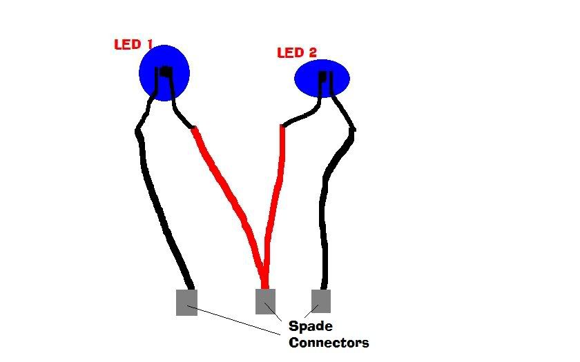
If the three connectors are B A C, A being the top one. AB never lights up. While AC turns on and off according to where the TPS is set.
If the three connectors are B A C, A being the top one. AB never lights up. While AC turns on and off according to where the TPS is set.
HAILERS
Joined: May 2001
Posts: 20,563
Likes: 27
From: FORT WORTH, TEXAS,USA
I have adjusted my tps (s5) before using the LEDs and now only one or neither light up no matter what I do. I think one of the wire going to the plug must be broken..
If the three connectors are B A C, A being the top one. AB never lights up. While AC turns on and off according to where the TPS is set.
If the three connectors are B A C, A being the top one. AB never lights up. While AC turns on and off according to where the TPS is set.
The other two go to the ECU. When the ECU puts a ground on these other two wires, one of the lights will light up. Those other two wires also have a wire spliced into them that leads to either the Relief solenoid or the Switching solenoid.
So you do like Roen said, and get a digital meter out and ohm out those other two wires from the green, three socket TPS check connector, to their respective pins on the ECU plugs.
That might take thirty minutes or so and then you'll know what is going on.
The engine should be fully HOT with the key to ON, engine off, when checking the LED's.
The Blue plug on the Relief solenoid should have power on it once the engine is hot, at idle and even with the key to just ON. Pull that plug off then back on and feel for a clicking of the solenoid as you do that. It should click. Means the ECU put a GND on that plug along with one of the two sockets on the green, three socket TPS check connector.
At the same time as described above, the Grey plug on the switching solenod should not have a gnd on it, so when you pull its plug on and off you feel no clicking of the solenoid.
So. IF your looking into the green, three socket TPS check connector, which of the sockets is B and C ? When looking into the sockets?
One wire should be Blue/REd and goes to the Switching solenoid AND pin 2O on the ECU. The other wire is Blue/Yellow and goes to the Relief solenoid AND pin 2P on the ECU.
So, knowing those two wires colors, and where the other end of those two wires terminates you can figure out which wire needs to be ohm'd out from point to point, and what their purpose in life is.
Did I mention the engine has to be fully hot? Yes. One LED does not light? Put it n the other hole and figure out if it's the LED or another thing.

Well here is the PM. I think I understand why you don't becuase they are not searchable.
And today I found out the the blue/yellow wire at the solenoid side is 12v while the black/white is nothing.
I didn't see any lose hoses.. and if I take the ground off the battery it never clears it from the ECU.
Another thing I noticed I was reading another on of your thread from back in 02 Where you were helping J-Rat with his 6ths. https://www.rx7club.com/showthread.p...elief+soleniod. It said you could watch the ports actuate without load. Well I tried this and nothing. I'll be Checking this.
Sorry to the OP for highjacking. But you seemed to have gotten your answer.
It's the relief solenoid.
Recently I had some friends put a RB header on my car (s5) and that is about when the dianogstics code 31 came up. Which is relief solenoid. Now I didn't have the ACV block off plate so the ACV is still on the car and as fas as I can see is connected correctly, outside the split air tube. The guy from RB told me I needed the plate but my car runs fine and I beleive I read others are running like this. I also didn't want to lose my 5th and 6th ports. Anyway I cut the check value off the split air tube because I didn't know if I could just stick a bolt in the hose connected to the ACV or what. So that hose isn't sucking air in or shouldn't be. So anyway, back to the relief solenoid.
I didn't get the code right away. And really I don't know what it does. But I'm getting sleepy now and really don't know what to add really. Is the relief solenoid not working bad? And although I will have probably looked at the FSM before I get your reply what should I look for?
Thanks, Eric.
I didn't see any lose hoses.. and if I take the ground off the battery it never clears it from the ECU.
Another thing I noticed I was reading another on of your thread from back in 02 Where you were helping J-Rat with his 6ths. https://www.rx7club.com/showthread.p...elief+soleniod. It said you could watch the ports actuate without load. Well I tried this and nothing. I'll be Checking this.
Sorry to the OP for highjacking. But you seemed to have gotten your answer.
HAILERS
Joined: May 2001
Posts: 20,563
Likes: 27
From: FORT WORTH, TEXAS,USA
Well here is the PM. I think I understand why you don't becuase they are not searchable.
And today I found out the the blue/yellow wire at the solenoid side is 12v while the black/white is nothing.
I didn't see any lose hoses.. and if I take the ground off the battery it never clears it from the ECU.
Another thing I noticed I was reading another on of your thread from back in 02 Where you were helping J-Rat with his 6ths. https://www.rx7club.com/showthread.p...elief+soleniod. It said you could watch the ports actuate without load. Well I tried this and nothing. I'll be Checking this.
Sorry to the OP for highjacking. But you seemed to have gotten your answer.
Something does not click here. The Relief solenoid has two wires. The black/white should have 12vdc anytime the key is to ON or better. The blue/yellow gets a ground put on it by the ECU when conditions are right. That's the way all those solenoids on the left side of the engine work. They have power on their black/white all the time and the OTHER wire gets a gnd put on it by the ECU when conditions are right.
Maybe you need to pull that relief solenoid plug off and look at the black/white wire with a meter again. Look for 12vdc. All those black/white are tied together inside the EM harness. So if you don't have it on the relief solenoid plug, go to another plug next to it and see if ITS black/white has 12vdc or not. It should. IF none have 12vdc on the black/white, then write back. Or look at the wiring diagram. The black/white wires go back to the Main Relay and from there back to the engine bay fuse box. ON series five I don't remember which fuse in the engine bay. EGI??? Take a look at the wiring diagram.
IF you look at page B1-b of the series five FSM you'll see the Relief and Switching solenoids wires are also spliced to the three wire,. green, TPS check connector. When that blue/yellow wire on the Relief solenoid gets a gnd from the ECU, then one of the sockets on the TPS check connector does at the same time. That ground is what makes a TPS light checker tool, light up at a given time. A fully warmed up RX-7, whether series four or series five. turbo or non turbo, will have a gnd on that blue/yellow wire at idle. If it does not, then either the TPS is rigged wrong or there is a problem with the ECU.
What happens is when the TPS is rigged right, it will output approx 1vdc to the ECU. The ECU will see this and in turn put a gnd on that blue/yellow wire. Make sense. Yes.
I don't do PM'S. It's better if I write online so when I make gross errors someone can correct them. Wayne used to do that function but he's gone ??? Iraq??? maybe.
Last edited by HAILERS; Dec 21, 2007 at 10:57 AM.
HAILERS
Joined: May 2001
Posts: 20,563
Likes: 27
From: FORT WORTH, TEXAS,USA
Oh. That post back years ago to JRAT. Yeah. That's series four. You have series five and they work different. Yours work off the airpump whereas the series four worked off exhaust backpressue. That post does not apply to you.
ON the 1986 stock series four I have, I've used a couple of methods to make the actuators work. I picked air of the airpump hose b/t the pump and the ACV and ran it to a common RX-7 solenoid. Then a hose from the solenoid to the tube that feeds the series four aux actuators. I used a Summit RPM switch to make the new solenoid trigger. Later I got a RTEK2.0 for n/a cars and I now use the RTEK to trigger the new solenoid.
That's really just a copy cat of how the series five aux actuators work. Off the airpump pressure is what I mean. And the ECU of the series five triggers the solenoid.
At one time I was using the gnd signal to the Relief solenoid to trigger the new solenoid at 3800rpm, but that method is FATALLY flawed. It turns out the Relief solenoid gets a gnd/loses a gnd, at numerous other times other than 3800rpm, so that did not work right.
I can't find page B-1b. The emmisions is F and engine is C. I'm looking at the rx7city copy. Anyway, I went back out there and checked it again. when plugged into the solenoid both are 12v when unplugged the black/white is 12v while the blue/yellow is ground. I checked continuty between the soleniod side of the plug and the TPS connector side it's good. So it seems the problem is with the soleniod is my guess. I hooked the solenoid up straight to the battery and it clicked.
Right now I'm leaving the thing unplugged Because the ECU doesn't need to be getting the 12v going to it.
BTW I haven't cleared the codes yet but the error 31 always shows back up when I do.
Right now I'm leaving the thing unplugged Because the ECU doesn't need to be getting the 12v going to it.
BTW I haven't cleared the codes yet but the error 31 always shows back up when I do.
HAILERS
Joined: May 2001
Posts: 20,563
Likes: 27
From: FORT WORTH, TEXAS,USA
When you are reading the blue/yellow and seeing voltage, you are back reading a voltage inside the ECU. In other words, what you read isn't relavant imho.
You need to heat the engine up. Then adjust the narrow band tps to output one volt dc going to the ECU.
The wiring diagrams I looked at I got off this forum for series five. I've no idea what that link is for a download.
You need to heat the engine up. Then adjust the narrow band tps to output one volt dc going to the ECU.
The wiring diagrams I looked at I got off this forum for series five. I've no idea what that link is for a download.
Maybe I'm not understanding but shouldn't the other solenoid (switching) also be 12v on the TPS tool plug? Which would make all three 12v. Which would mean the LEDs wouldn't work. I'll play with in when I can in the next day or so and see if I can get it to work.. But don't understand how it's going to change from 12v to ground.
But thanks a lot for all your help..
But thanks a lot for all your help..
HAILERS
Joined: May 2001
Posts: 20,563
Likes: 27
From: FORT WORTH, TEXAS,USA
No. The only wire in the green, three socket TPS plug, that has power is the one with the black/white wire. The other two wires get a ground signal from the ECU. It's that ground signal that makes the LED test lights come and go.
If one took a meter and put it's neg probe on a ground and the positive lead on one of the two wires in the TPS check connector, he most probably will read 12vdc on them, BUT that 12v is just you back reading thru the coil on the Relief or Switching solenoid coil. Normal as apple pie.
Or another way of looking at things. All three TPS sockets will read 12vdc if the ECU is NOT putting a ground on the Switching or Relief solenoids. When the ECU does put a ground on either of these two solenoids, then the wire in the TPS check connector that relates to that solenoid will drop below 2vdc.
Or put another way.......go pull the grey and blue plugs off the two solenods. NOW no matter what, those two wires that relate to those solenoids will never read 12vdc .
I'm trying to say in several ways, that the 12vdc you see on the blue/red, blue/yellow wires in the TPS check connector, is nothing more than back reading thru the solenoid coils to the black/white wire on the Relief and Switching solenoids. When the ECU puts a gnd on those two wires, the voltage will drop down to below 2vdc.
Or put another way...............you should not be in anyway concerned with seeing 12 on the blue/red, blue/yellow wires in the TPS check connector, if your using a set of LED'S to set the TPS.
IF your using a digital meter to set the tps, then put the meters negative lead on the batterys gnd terminal or other known gnd, and then put the positive lead in the blue/yellow or blue/red. You will register less than 2vdc on the blue/yellow when the TPS is set right and read 12vdc on the blue/red when the TPS is set right.
But if your going to use a meter to set the TPS, just plain forget that TPS check connector. That's just a waste of time and effort. Go directly to the TPS's plug and backprobe the green/red wire on the harness side of the TPS connector. The plug must be connected up. You DO not pull the plug apart. Then when you see approx 1vdc on that green/red wire, the TPS is set. Takes but a moment to do that.
Got a turbo and it's too hard removing the intercooler to get to the TPS plug? Then go to Radio Shack and buy a bannana jack and piece of wire a half foot long and solder it to the green red wire and put the jack somewhere it's accessable with the intercooler on. Or buy a RTEK and look at the TPS setting on the Palm and adjust the TPS screw while looking at the Palm screen.
The engine must be HOT doing the TPS adjustment...........although there is way around that. I'm just tired of typing.
Or put another way....the next time you see 12v on the blue/red or blue/yellow at the TPS check connector, reach over and pull the blue or grey plug off the two solenoids. The 12vdc will go away.