
Sureshot wiper fix

Sureshot wiper fix
I was looking at the post that had the way that Sureshot used to fix the wiper switch, but the thread's pictures aren't showing up. I was wondering if anyone had pics of what he did since I think I may have messed up the traces on my switch.
Former Moderator. RIP Icemark.
Joined: Apr 2001
Posts: 25,896
Likes: 24
From: Rohnert Park CA
Jpk3200
Joined: Oct 2006
Posts: 824
Likes: 0
From: San Antonio, TX
I would take out my ohmmeter, and start testing connections that you think might be screwed up. Make sure you didn't accidentally solder joints together. Jumper connections with a wire where you might have lifted the trace off the board.
Former Moderator. RIP Icemark.
Joined: Apr 2001
Posts: 25,896
Likes: 24
From: Rohnert Park CA
mist stopping just stopping when turned off usually indicates that the relay #1 didn't get replaced correctly.
You probably ripped out traces at the relay holes when you removed the old relay.
You probably ripped out traces at the relay holes when you removed the old relay.
I had dammaged traces when I did my wiper switch fix. All of the traces are surface and fairly easy to see. Did any little ring's come out still on the old relay? If so, those would be the pin's on the new relay that need to be jumpered to their destinations. If no rings came off or you don't know which pins are dammaged you'll have to go the multimeter route. Just follow the surface traces.
Trending Topics
One of the rings did come out when I was removing it, I tried to use a jumper but I guess I'm not doing it right. Is there somewhere I can see where each pin on the relay goes because I tried putting a jumper where I thought the pin went but I guess I was wrong.
Former Moderator. RIP Icemark.
Joined: Apr 2001
Posts: 25,896
Likes: 24
From: Rohnert Park CA
What pin pulled? I can tell you where it goes.


That will be your problem. Once Icemark tells ya where it goes you should be good. I know I pulled that one too but I did my fix over 8 months ago and I don't remember where it went. I would check the pin next to it too and make sure it's ok.

HAILERS
Joined: May 2001
Posts: 20,563
Likes: 27
From: FORT WORTH, TEXAS,USA
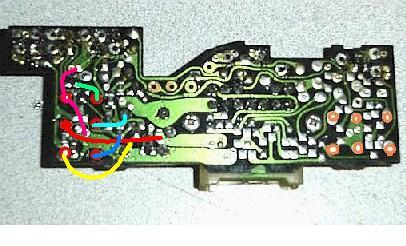
Use the new relay you bought. Now you get some small gauge wire and solder a piece of it to each trace or remnants of the trace. Six wires total. The other end of the six new wires will now go to a pin on the new relay. Just match the new relay with where it WOULD have gone on the board. You can locate the new relay fairly near the old location.
A somewhat dark jpg attached of what I did. It works, but this cluster is just a spare I don't use on a daily basis
EDIT: Added a second jpg.
Last edited by HAILERS; Feb 8, 2008 at 06:59 PM.
HAILERS
Joined: May 2001
Posts: 20,563
Likes: 27
From: FORT WORTH, TEXAS,USA
The new relay only fits in the board one way. So. If you hold up your new relay (assuming it's identical to the old relay) you should be able to figure out where the new wires would go. Like in the jpg attached, the relay has two prongs seperated from the other four prongs on the relay. So it should be easy to look and see that, yes, those two go to the two on the board that are seperated from the other four. So run a wire from the two holes on the board to the two prongs on the new relay.
Maybe my pictures are too dark. The copper looking thing is the new relay. There are six black wires going from it to the board.
If your using some auto relay not similar to the factory ones, then just ignore this post.
Former Moderator. RIP Icemark.
Joined: Apr 2001
Posts: 25,896
Likes: 24
From: Rohnert Park CA
OK, guys don't flame me for this but I think I might have ruined another trace. I feel like such a noob because I have decent experience with soldering but for some reason I messed up a bit with this project. Once again the zero is where I think I messed up. It might be safer to show me where all the points go that way I can stop bothering you guys with my mistakes lol.
/ /
0 /
/ 0
/ /
0 /
/ 0
I haven't got a chance to yet but I saw some more copper rings because I had to remove the relay because I accidentally shorted some leads and ruined the new relay. I had a second one, but when I took the old one out there were more copper rings on the pins of the relay.
Ahhh, ic ic. Well if you can't see the traces and Icemark hasn't replied by tomorrow i'll be pulling the rest of the interior out of my car so i'll look at the traces for you and post it for ya.