When you click on links to various merchants on this site and make a purchase, this can result in this site earning a commission. Affiliate programs and affiliations include, but are not limited to, the eBay Partner Network.
I'm going to try the TXL for now, but will be using Tefzel mil spec shielded for the wires that require this (knock, O2, and CAS). The goal is still to keep it as OEM as possible. Tefzel throughout may be version 2.0.
the factory harness (made by Yazaki), is like this too, the important stuff is nicer and has a better wrap than the dumb stuff. probably done for cost savings, do you need the fancy wire for the water temp sensor? or the fan switch?
the factory harness (made by Yazaki), is like this too, the important stuff is nicer and has a better wrap than the dumb stuff. probably done for cost savings, do you need the fancy wire for the water temp sensor? or the fan switch?
Absolutely. I'll be getting into factory harness deconstruction very soon. The factory shielded bundles are massive, particularly the CAS.
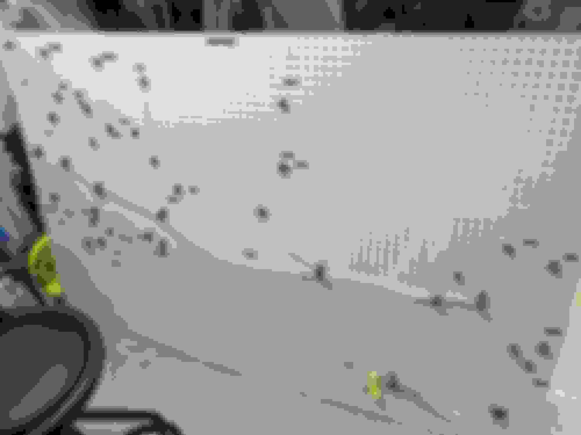
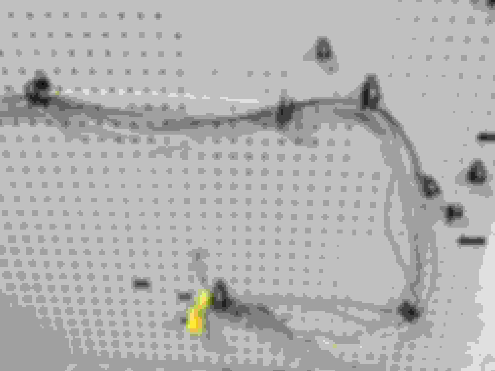
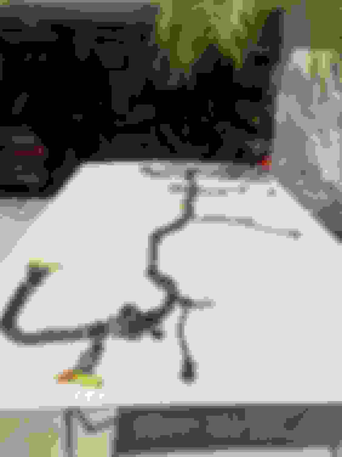
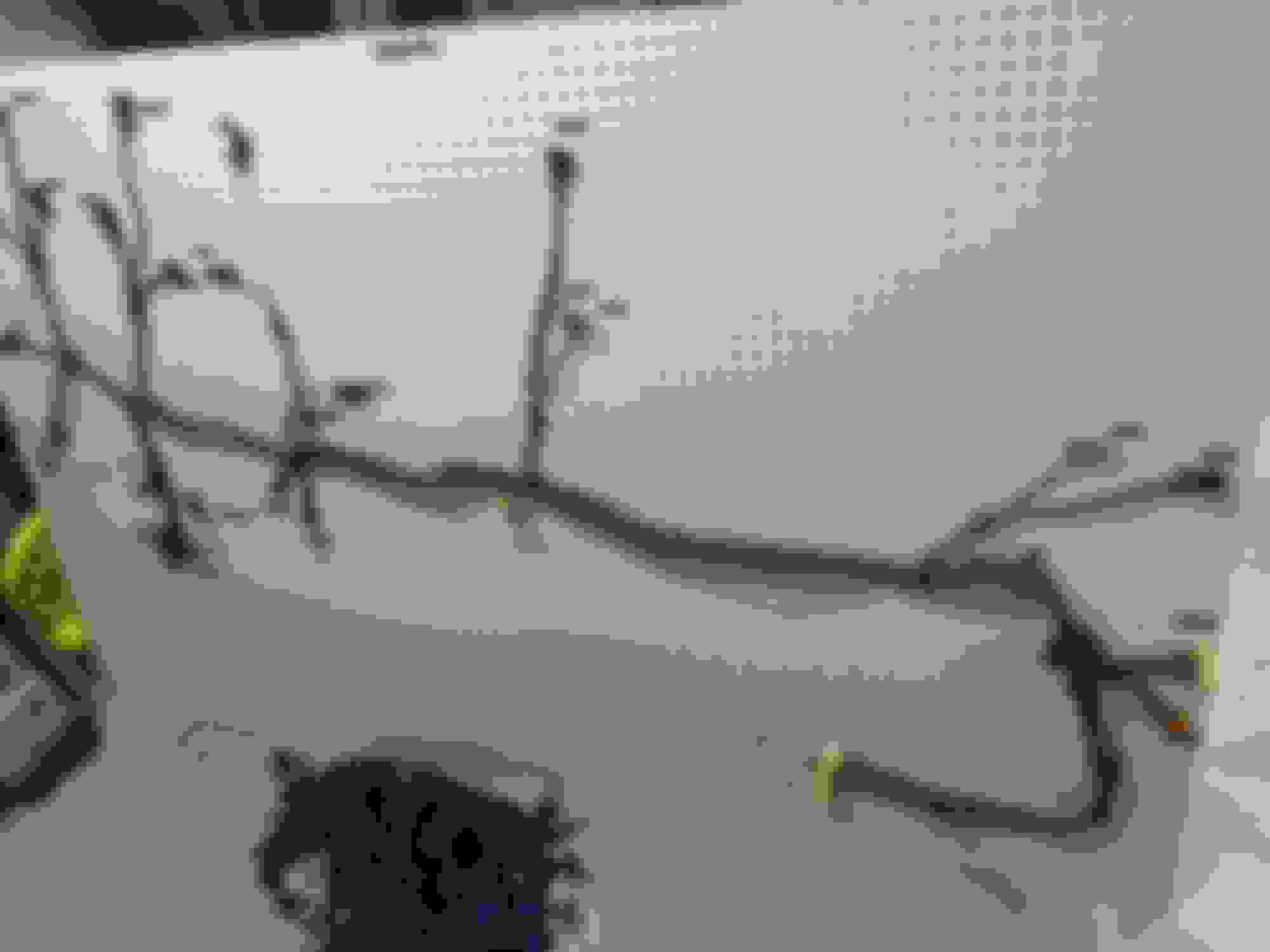
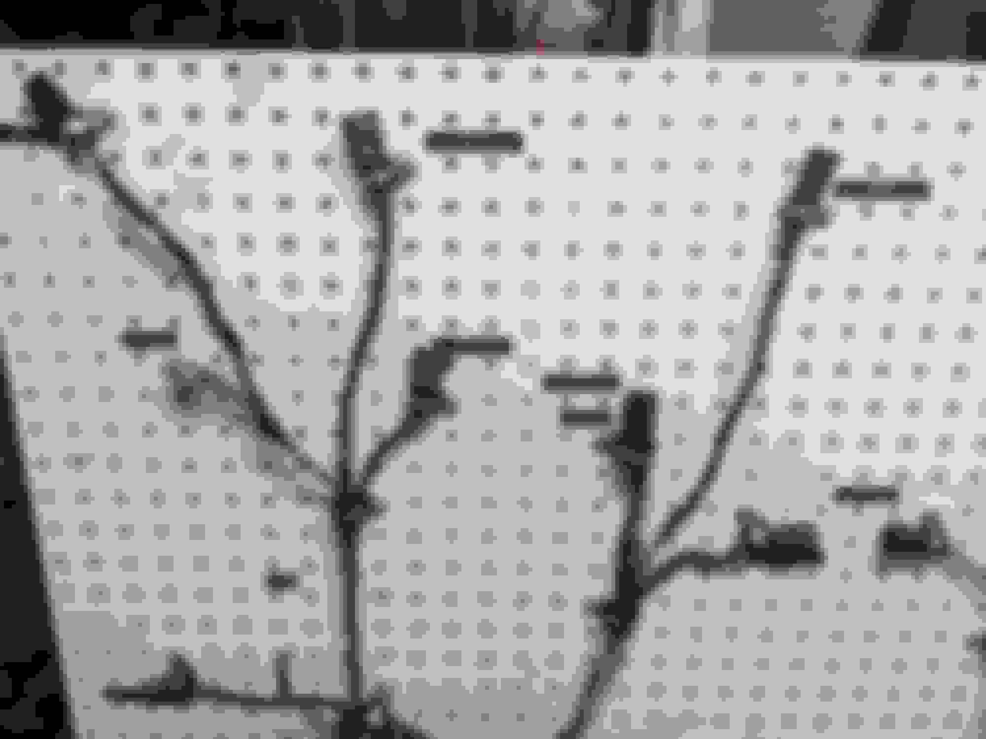
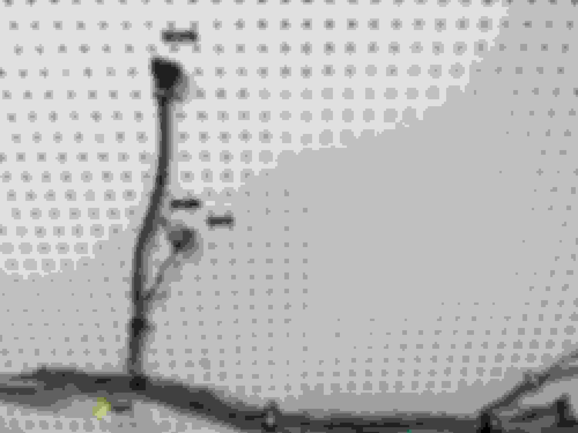
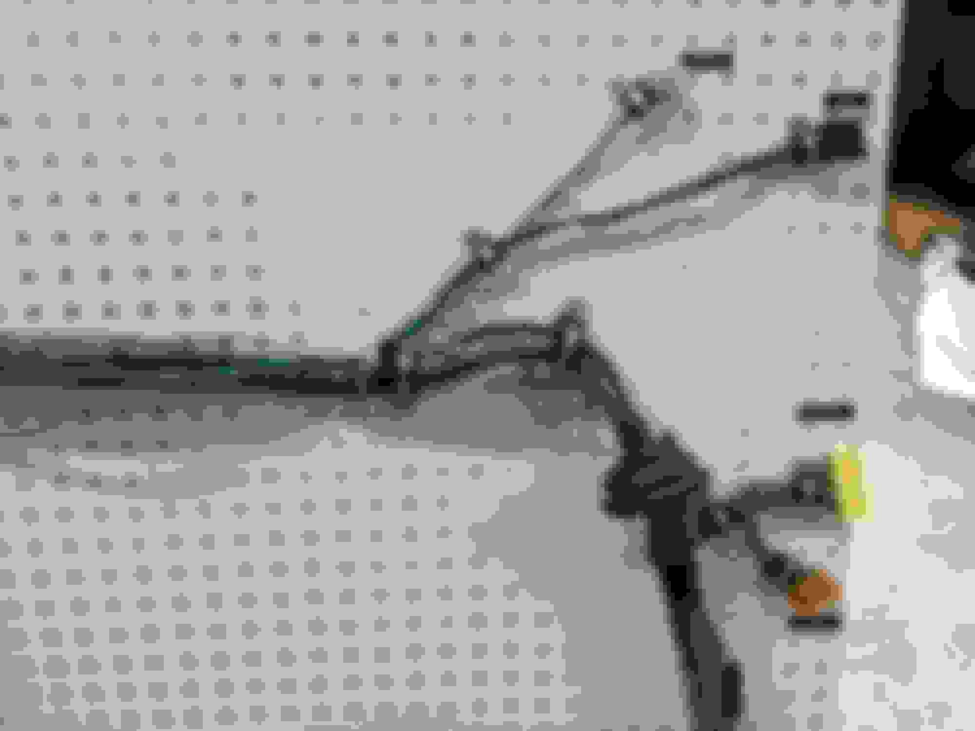
So, last weekend's project was getting the harness mounted to some pegboard for measuring/labeling/deconstruction.
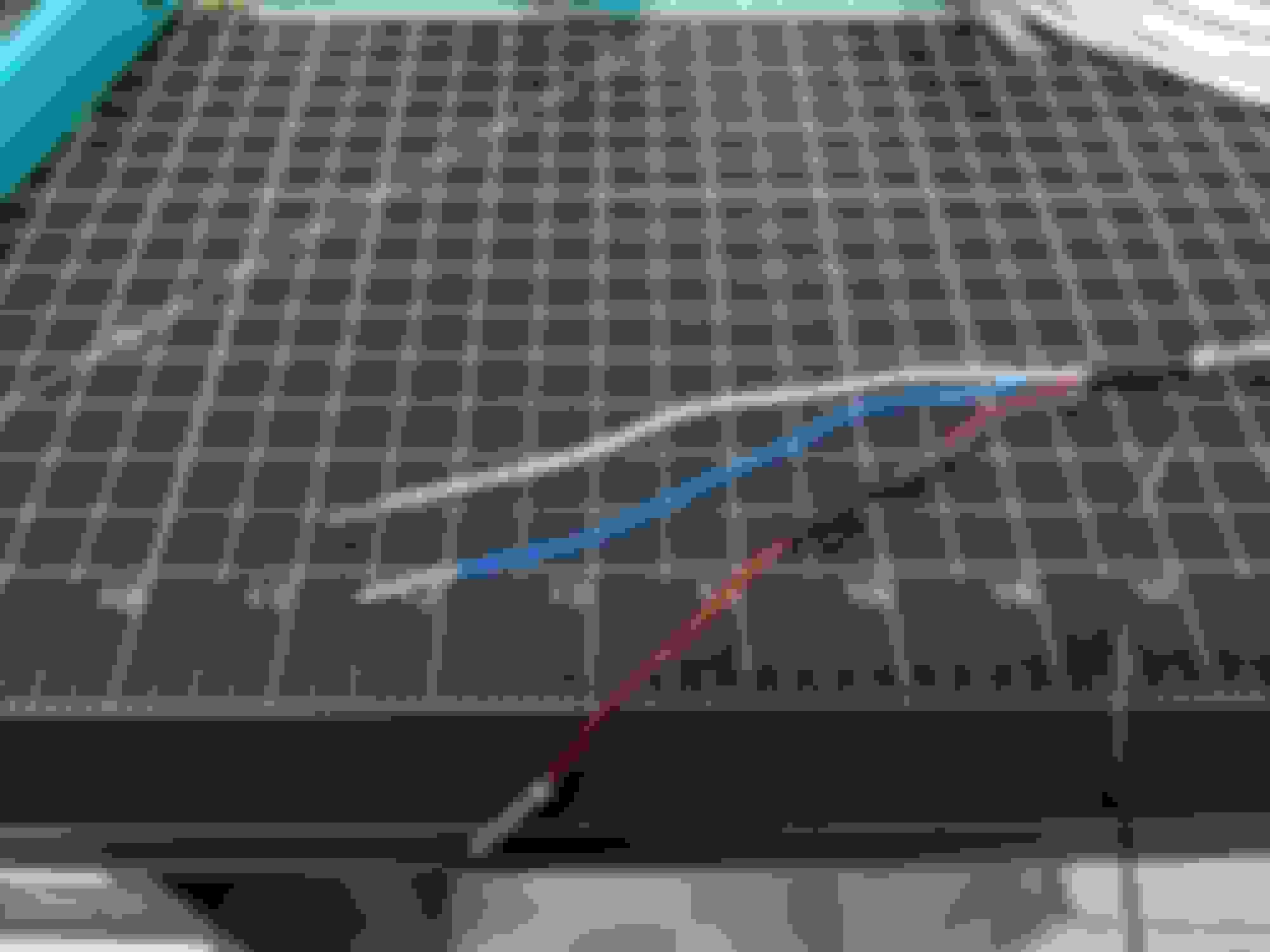
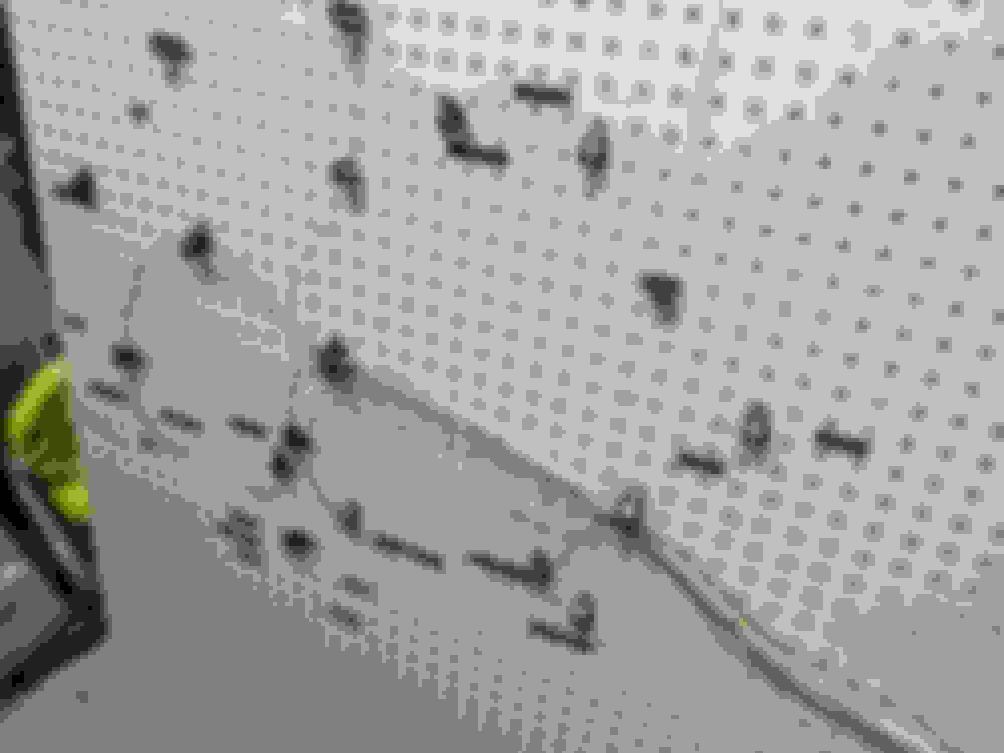
This morning, I did some unwrapping. You can always tell there are splices by simply looking at the wiring diagram, but it's nice to know where the factory did them.
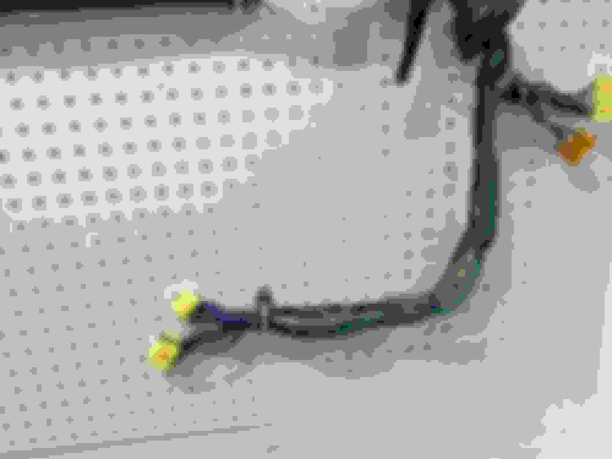
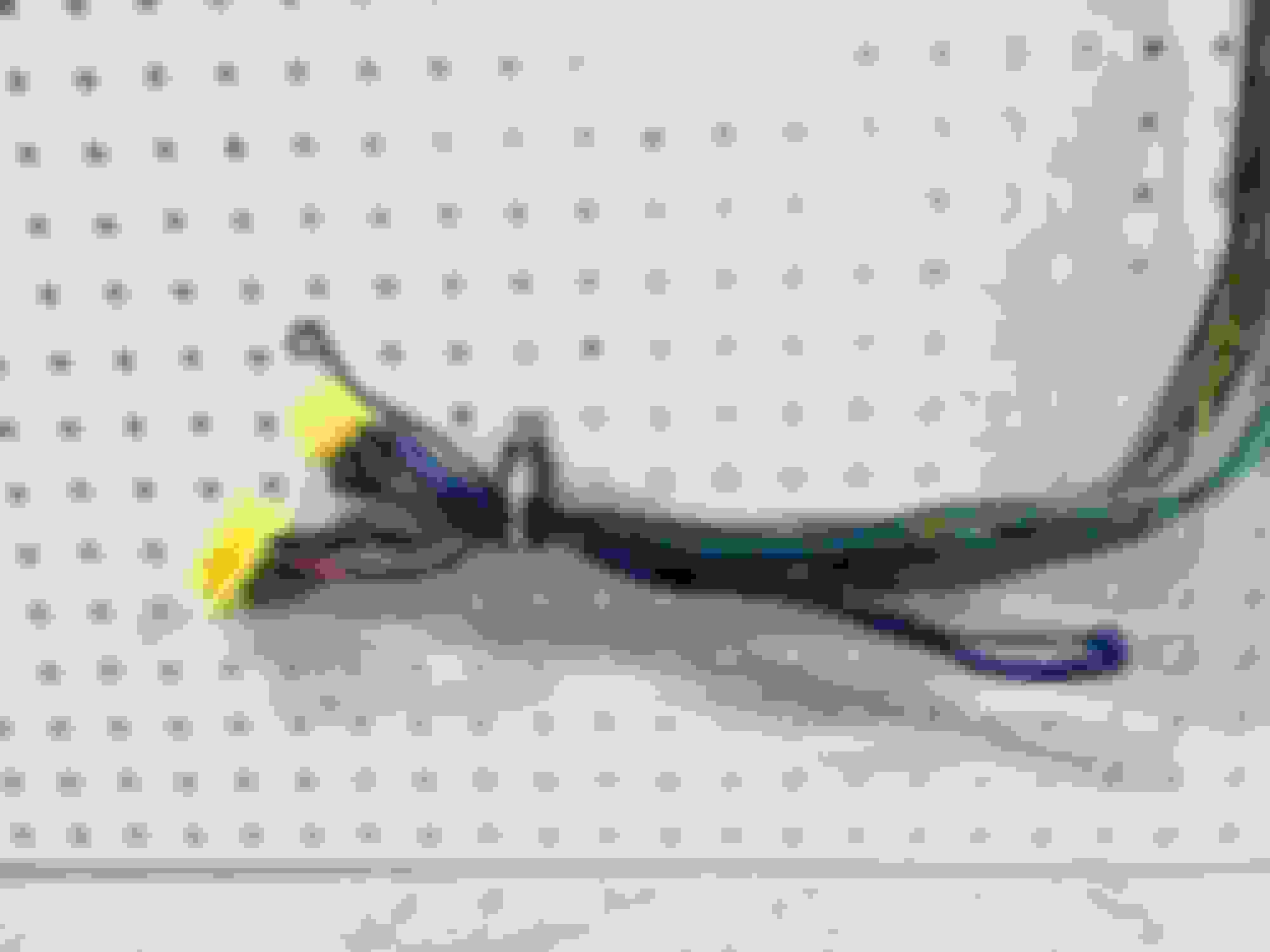
Green and red wires from the four wire CAS shielded bundle spliced to only the red wire right before the ECU connector.
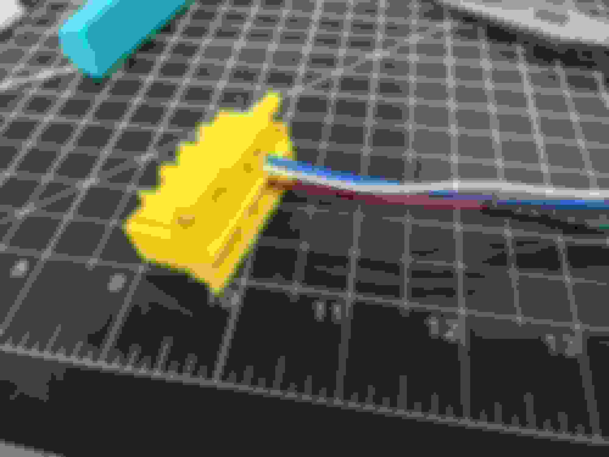
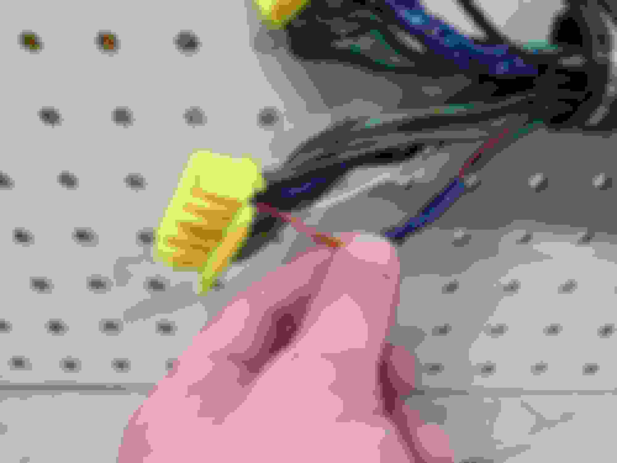
Black with white wires spliced into a common ground wire.
I haven't unwrapped this yet, but shielding grounds from the knock sensor, O2 sensor, CAS, and AFM.
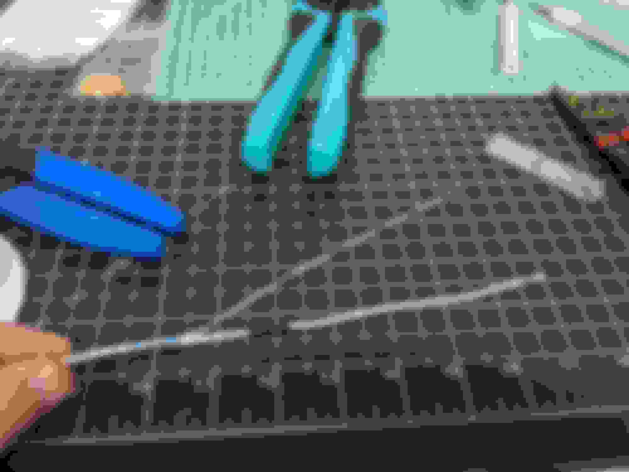
Brown with blacks spliced into each other. These are sensor grounds.
More sensor ground splices.
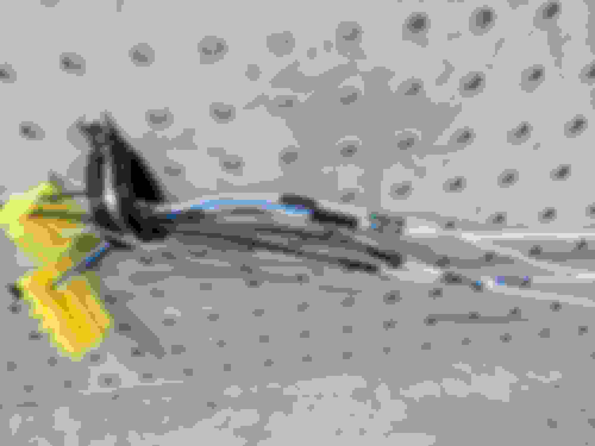
Working with 30 year old tape is fun! It's incredibly sticky/gooey. I did get more than just what's inside the vehicle unwrapped, but there is nothing special about what I've undone there.
I should be able to start building soon. I need a few other random supplies, but one is rather important. I forgot to buy a four conductor shielded wire for the CAS. Currently it's out of stock at ProWire (at least the 20 AWG is).
Finally time to continue on as I have gathered the last remaining supplies I wanted to make this harness.
The old, stock harness has been mounted to the pegboard, clamped down, and everything labeled. I have also removed all of the old tape and coverings. I have marked where breakouts were with some fabric Tessa tape.
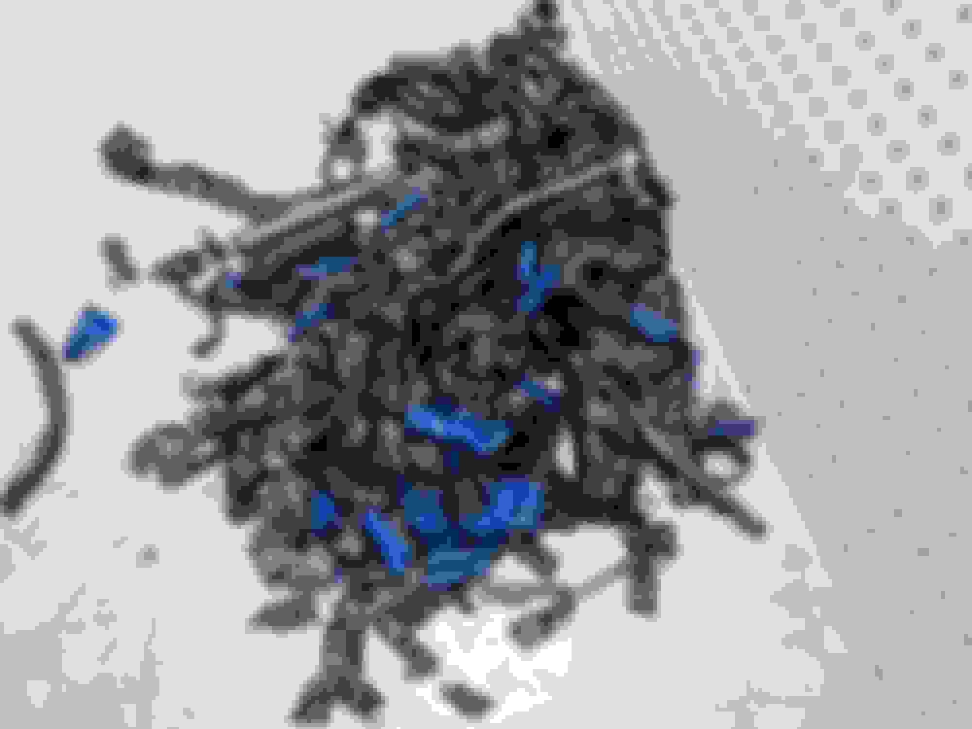
Here is what a pile of 30 year old tape looks like that used to cover an emission harness:
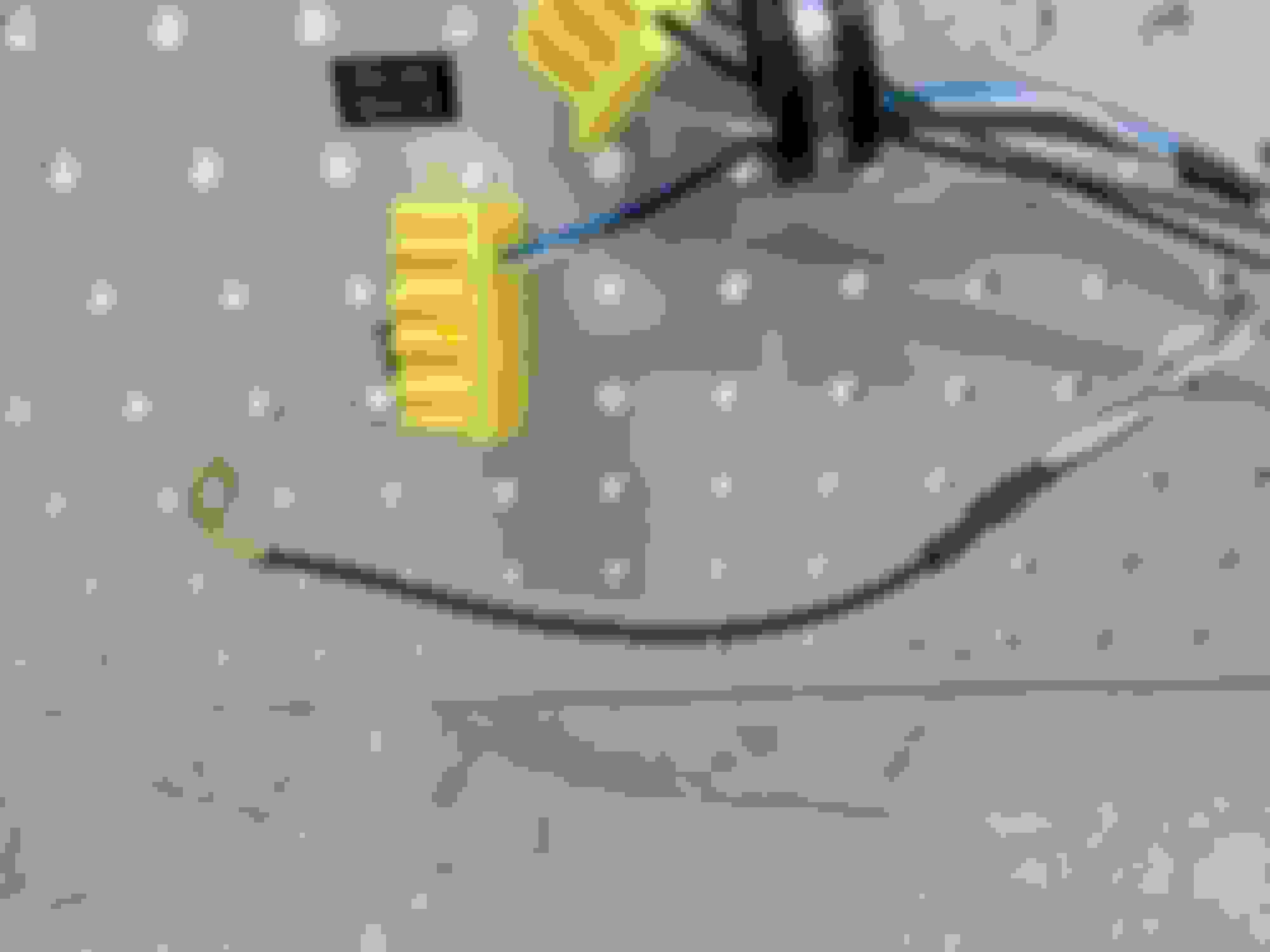
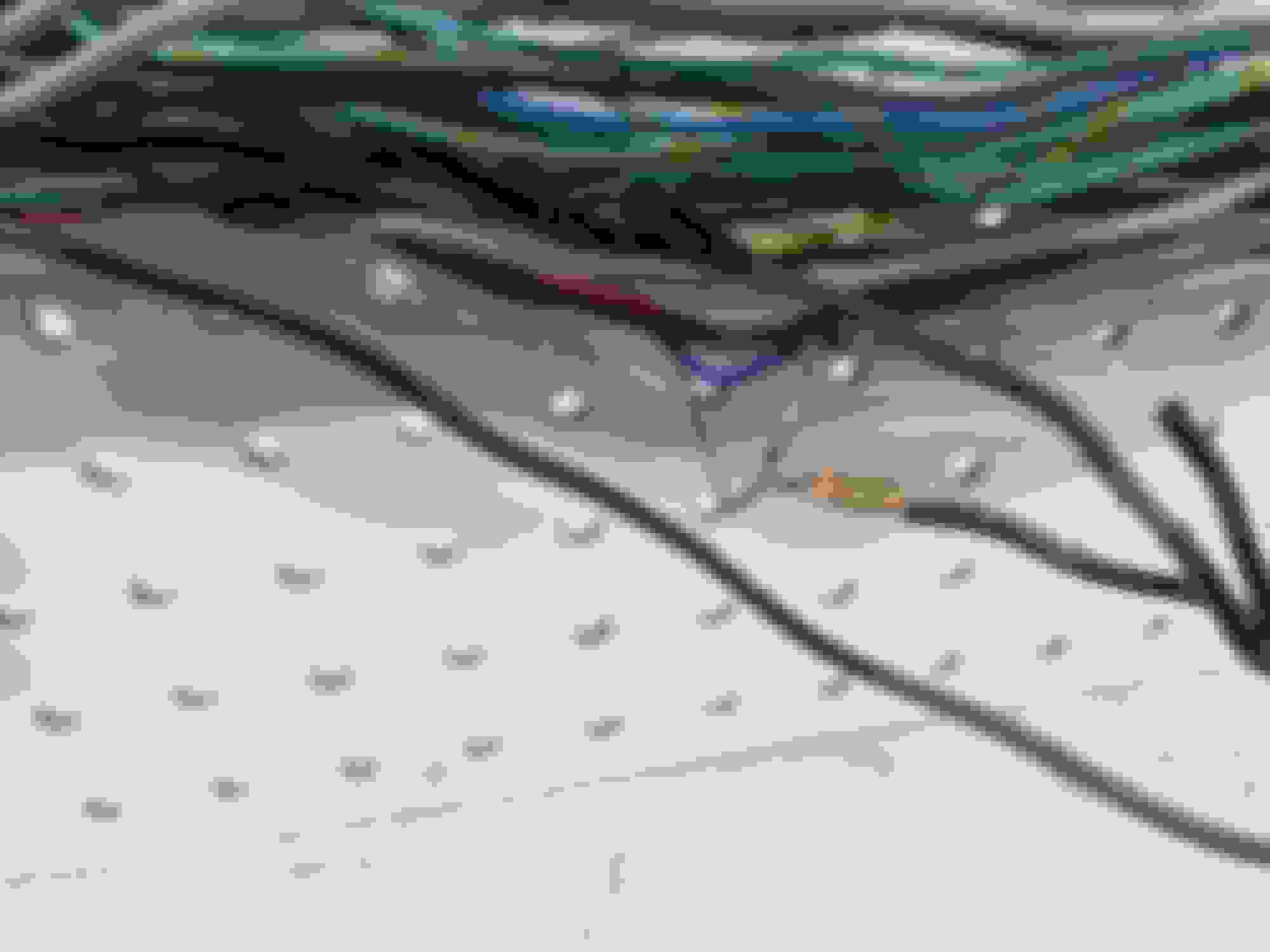
Here is how the stock harness grounded the shield wires. There are much better ways to do this now with shield terminators.
The pegboard is a bit of a makeshift harness board like professionals would actually use. I still will have the stock one for reference, so I'm confident in not screwing up any wire lengths. Measure twice or even three times, cut once.
The weather is going to be great here this weekend. It will be a nice couple of days to work in the garage.
Finally time to continue on as I have gathered the last remaining supplies I wanted to make this harness.
The old, stock harness has been mounted to the pegboard, clamped down, and everything labeled. I have also removed all of the old tape and coverings. I have marked where breakouts were with some fabric Tessa tape.
Here is what a pile of 30 year old tape looks like that used to cover an emission harness:
Here is how the stock harness grounded the shield wires. There are much better ways to do this now with shield terminators.
The pegboard is a bit of a makeshift harness board like professionals would actually use. I still will have the stock one for reference, so I'm confident in not screwing up any wire lengths. Measure twice or even three times, cut once.
The weather is going to be great here this weekend. It will be a nice couple of days to work in the garage.
I�ve often wondered what the total cost of doing it yourself like this would be? After buying new wire, new connectors, special tapes, heat shrink and that meshy stuff I see folks use. Versus paying someone to do it. Is it half the cost or even cheaper? What�s the tally looking like Jerry and does it require special crimpers or any extra tools?
thanks!
btw excellent detail in your post, and sharing this with the community!
I'll do my best to keep a tally of what all ends up being used on the harness to come up with a material cost. My original estimate is that I may end up with about $500 of material in this harness, but that will be influenced a lot by how many feet of wire is used (I ordered 25 ft of each wire, vastly more than needed for one harness) and also total length of heat shrink and expandable braid.
However, as you've alluded to, there's tools needed that if you don't have add to the cost. Open barrel crimpers are a must. I have tried a few over the years. I think I have a new favorite that I recently picked up. In fact, I think a quick comparison of all the crimpers I have would make for a great next post. I've got lots of extra wire and terminals.
Agreed I'd be curious about the crimpers you end up using, I only have the basic un-insulated\insulated klein crimpers. For doing things like crimping those cheap butt connectors etc. I've eyeballed some of those open barrel ones but never really been sure which ones were worth while, nor have I had a true need YET. Sounds like if you end up @ around $500, that's half of what I've been quoted for a haltech terminated harness, which I assume is going to be similiar-ish .
BTW do you come up and DGRR in NC? I haven't been yet but sure want to meet some of you folks one day.
I went to DGRR this year rotary-less in my daily driver Mazda 6 since I had just discovered the coolant seal issue. My plan is to make it back in 2022 with the RX-7. My wife was like, "You want to go back?!" Uh, yeah, I never made it with the car I wanted to, haha.
So, let's talk tools. The first things are obvious. You need some cutters. I have these Craftsman Professional cutters I've been using for 20 years and recently added this pair of Kleins.
Wire strippers. I had been using a companion set of wire strippers that came with those Craftsmen cutters up until earlier this year. The Klein automatic strippers were life changing. Not sure why I never bothered upgrading until now.
I also recently upgraded to a cordless heat gun. Attachments to better direct flow and also to help with heat shrink are a must.
Terminal extraction tools. These are pretty great and have worked for a lot of things. Tiny flat head screwdrivers can work for a lot of things too.
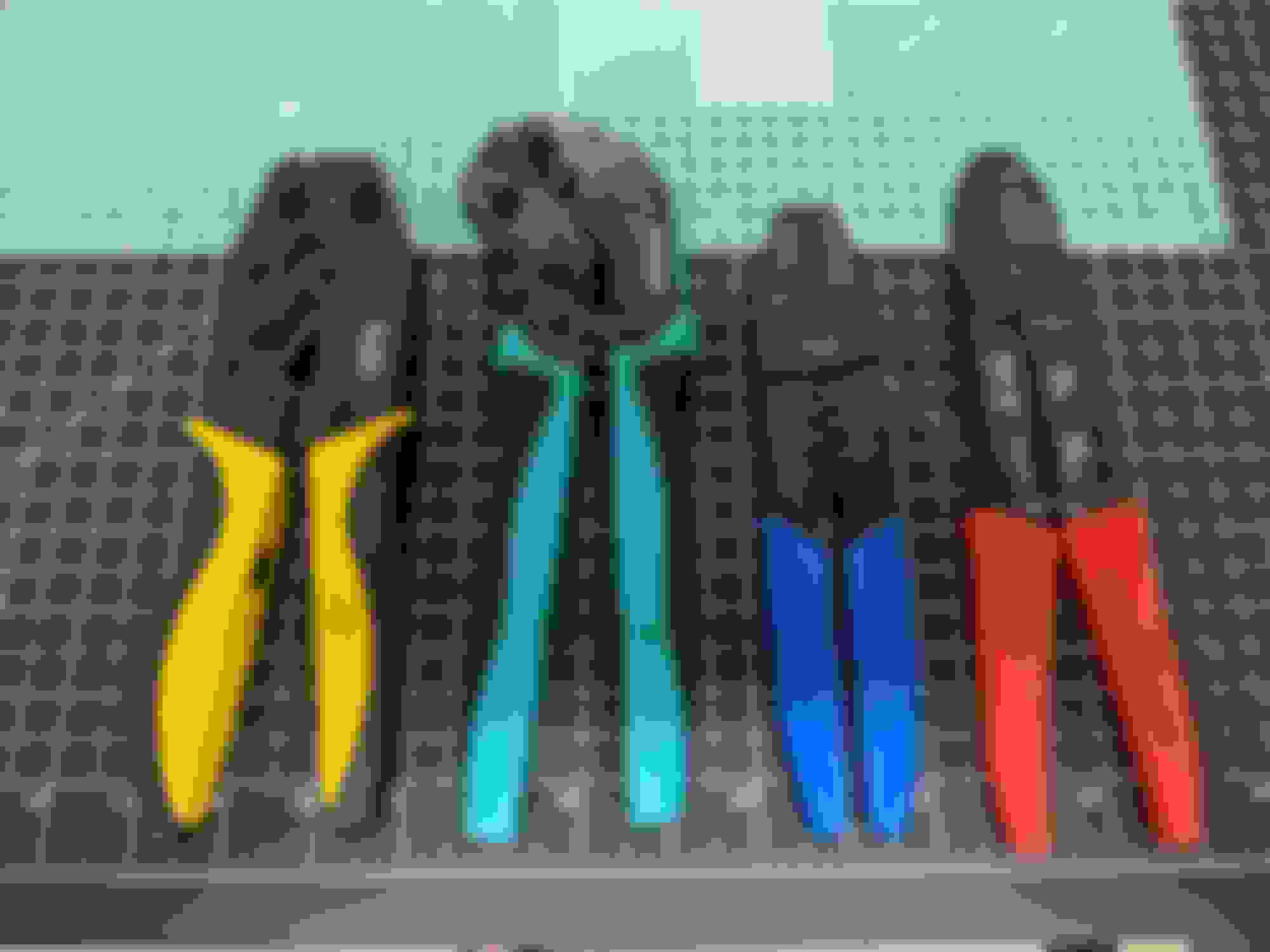
From left to right that's a pair of Klein ratcheting crimpers, a pair of Pro's Kit ratcheting I picked up from Corsa-Technic (with die set CDIE2 installed), a pair of non-ratcheting Hozan crimpers I bought from Ballenger Motorsports, and a pair of Hero non-ratcheting I bought ages ago from Eastern Beaver.
Let's look at the crimps:
First up is the Klein's. I can't seem to dial these in very well. I've backed off on the ratcheting pressure and that helped. It's a decent crimp, but a little deformed. Certainly not the greatest. Both ratcheting sets do both the conductor and insulation crimps at the same time.
Next up is the Hero's. These and the Hozan require two steps to both the conductor and insulation. I got by with this crimper only for a long time, but these crimps aren't great anymore. I don't know if it's been overused and partially damaged by me or what, but this is currently the least favorite one I own. Now that I look closely, you can see the 0.3 and 0.5-0.85 almost look rounded. These are probably junk at this point. That's not a knock on them, just overuse and possibly some misuse.
Next, the Pro's Kit. These are good, solid crimps with a tiny bit of deformation. It didn't take much dialing in to produce a decent crimp right away.
Finally, the Hozan's. This produces probably the prettiest crimp. They are fairly thin and require near perfect placement to get all of the terminal to crimp, otherwise you may have to perform the crimp a second time (as I did in this one, you can probably see where).
For this, I'm probably going to use a combination of the Pro's Kit and the Hozan. The die set I am using on the Pro's Kit specifically says not compatible with one terminal type I am using (Tyco AMP Econoseal Mk-II J series). The Hozan crimps are so good looking but require a good bit more time to perform. Both the Hozan and Pro's Kit crimps are solid and I have complete confidence in them. I have given them a lot of pull tests and nothing came out.
It was fun testing that out. I needed a label maker anyway, so I made sure to get one compatible with heat shrink reels. Going to label all the connectors like a some sort of professional.
I got started this afternoon and have all the shielded wires done and wired in at the ECU connectors. Post on that coming sometime tomorrow. It's now quiet relaxation time for the rest of the evening.
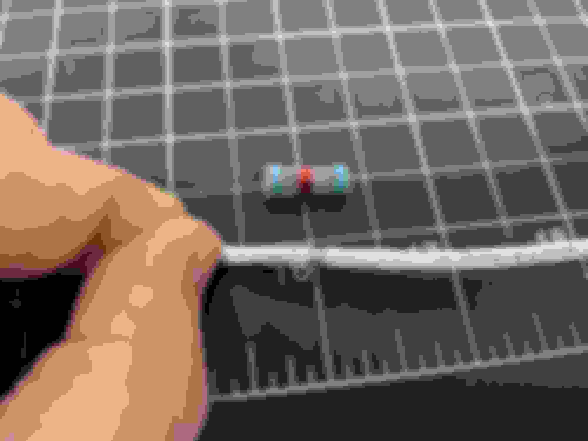
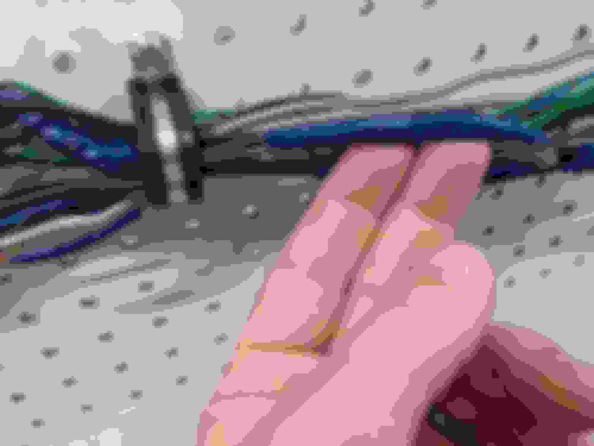
So, shielded wires need to be grounded for the shield to be effective. I started with the four conductor shielded wire for the crank angle sensor. I stripped about eight inches away of the outer insulator and the shield.
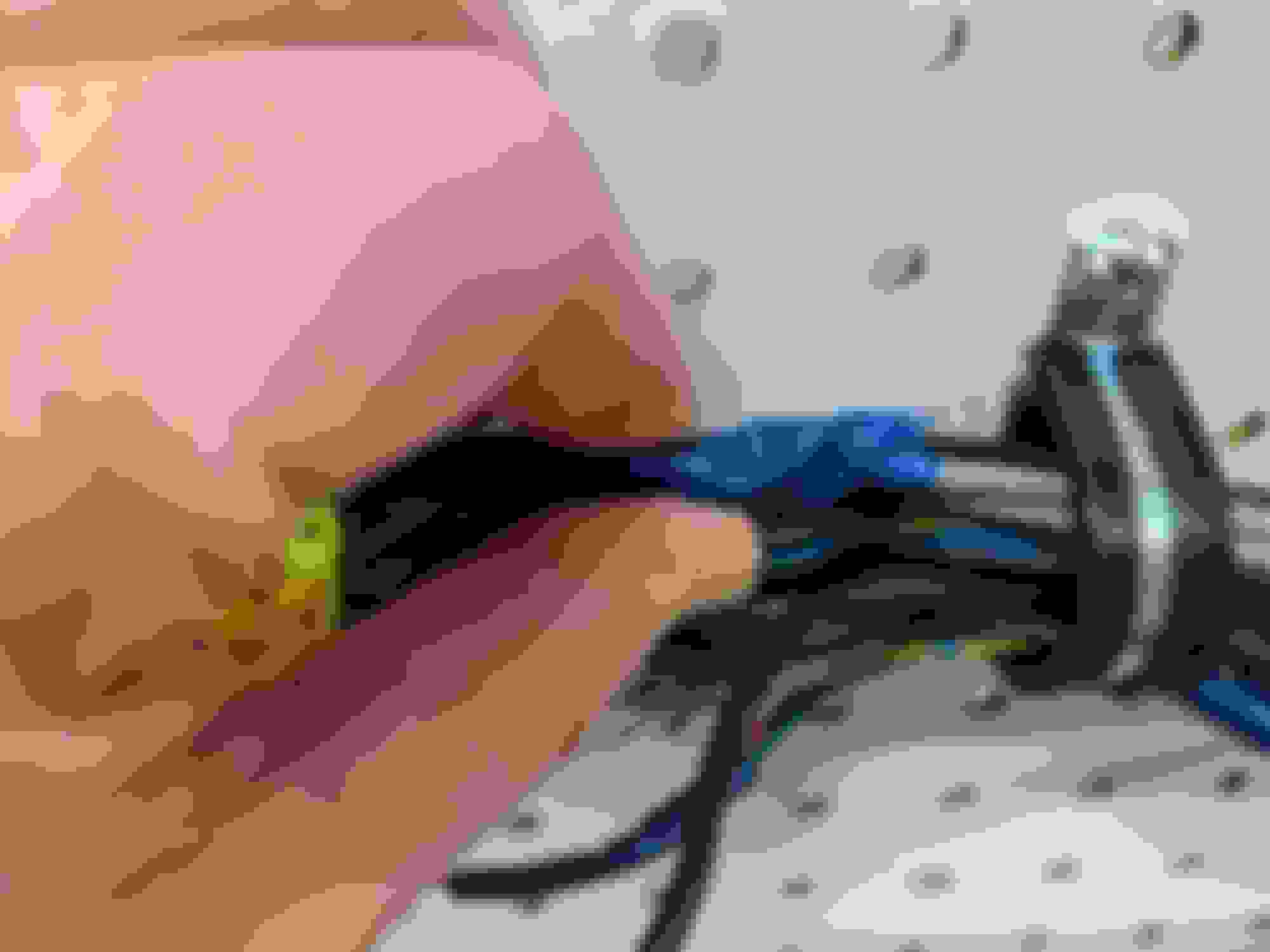
Here's the shield terminator and I've also removed a small section of outer insulator to expose the shield
:
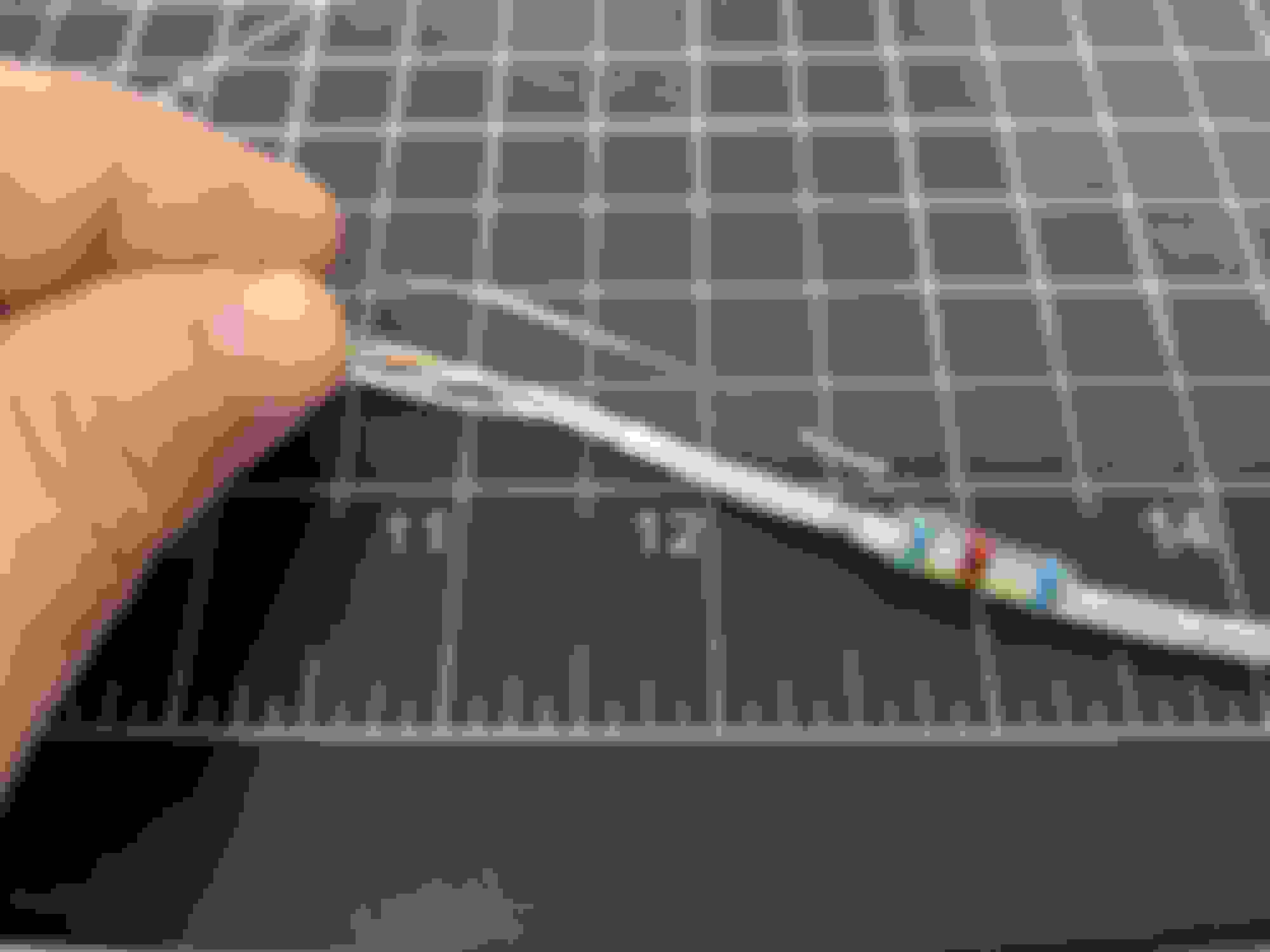
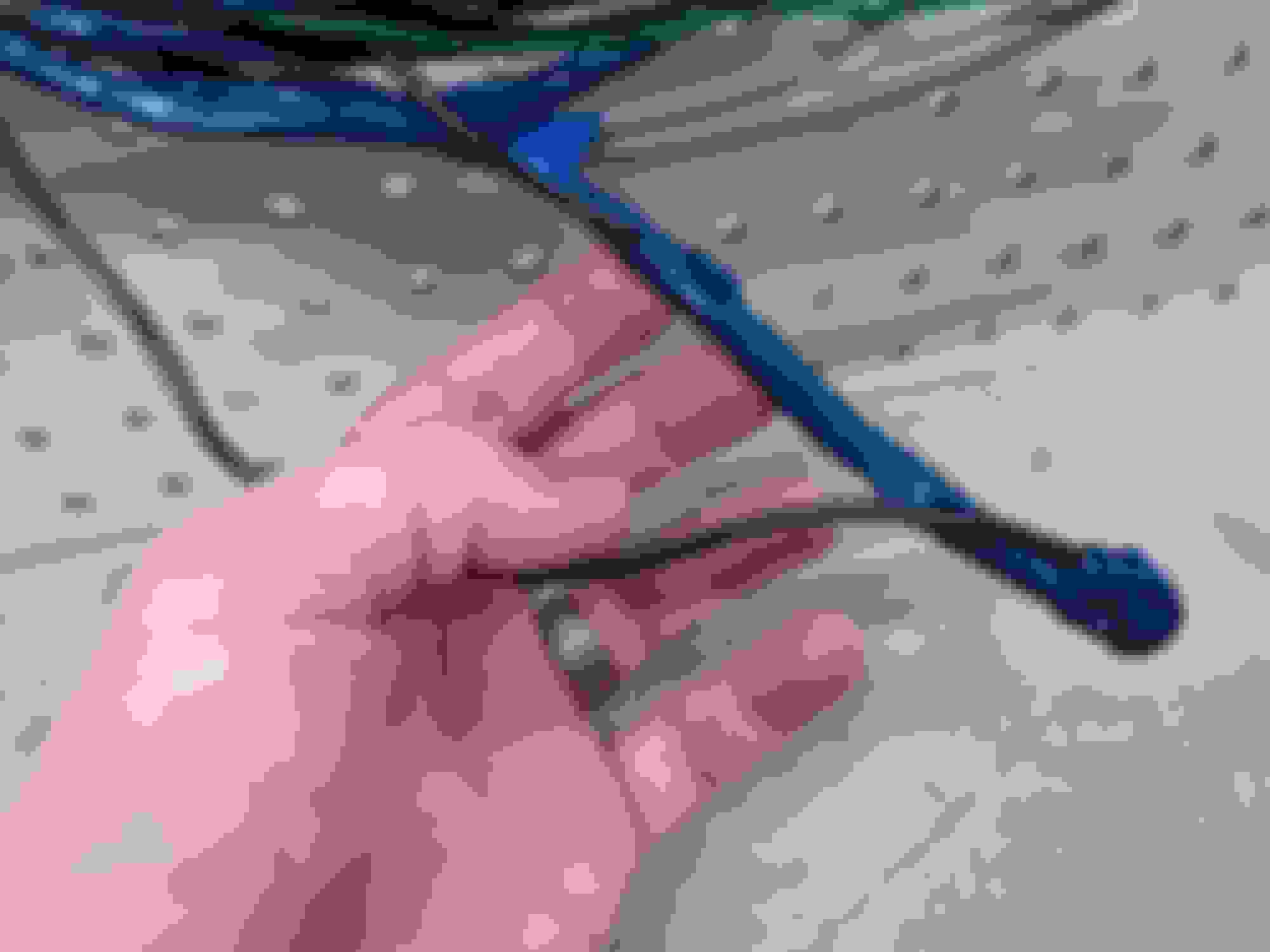
Ground wire inserted and then apply heat:
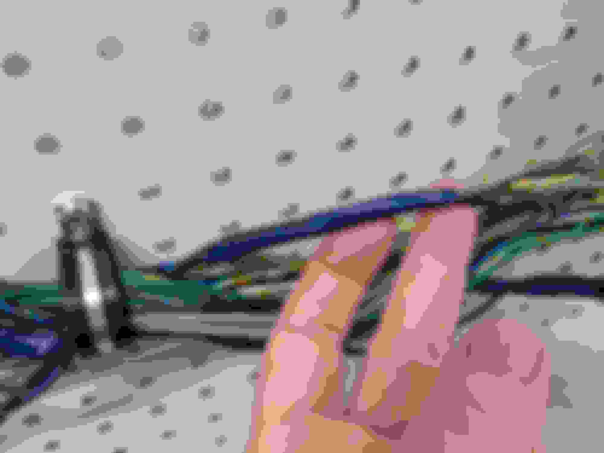
I wanted stock wire colors, so the smallest of colored heat shrink was applied to the individual strands. The red and green get terminated together right before the ECU, or split apart after the ECU, whichever you prefer to think of.
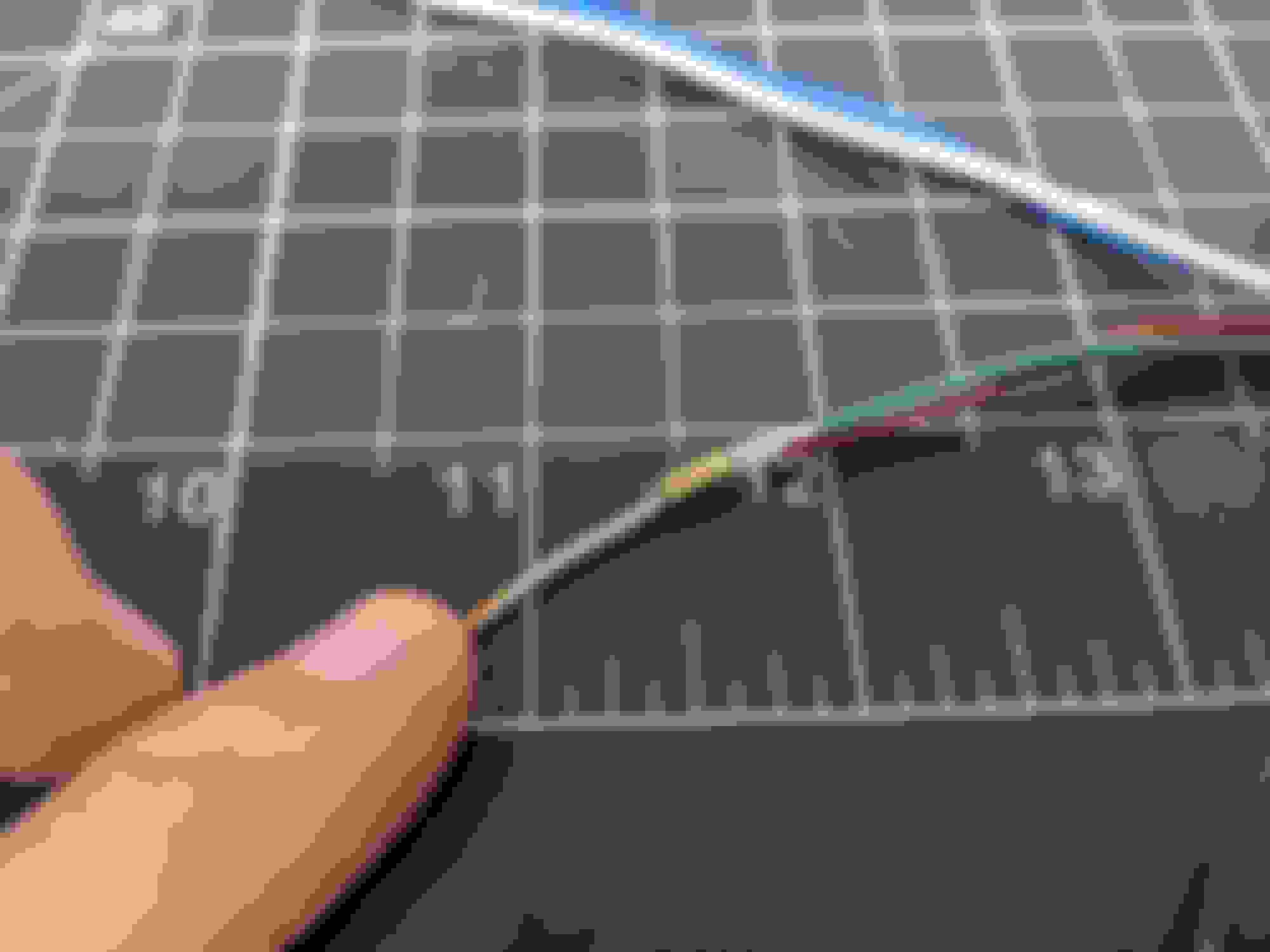
That's a little bit of Raychem SCL heat shrink applied at the splice and also around where I've peeled the outer insulator and shield away from the cable. SCL is adhesive lined to make the connection moisture resistant.
Stay hydrated:
Terminals for the ECU connector crimped on and then into the connector:
Repeat three more times, but these are single conductor shielded wires for the knock sensor, oxygen sensor, and the air flow meter. The shield terminators for these have preinstalled ground leads.
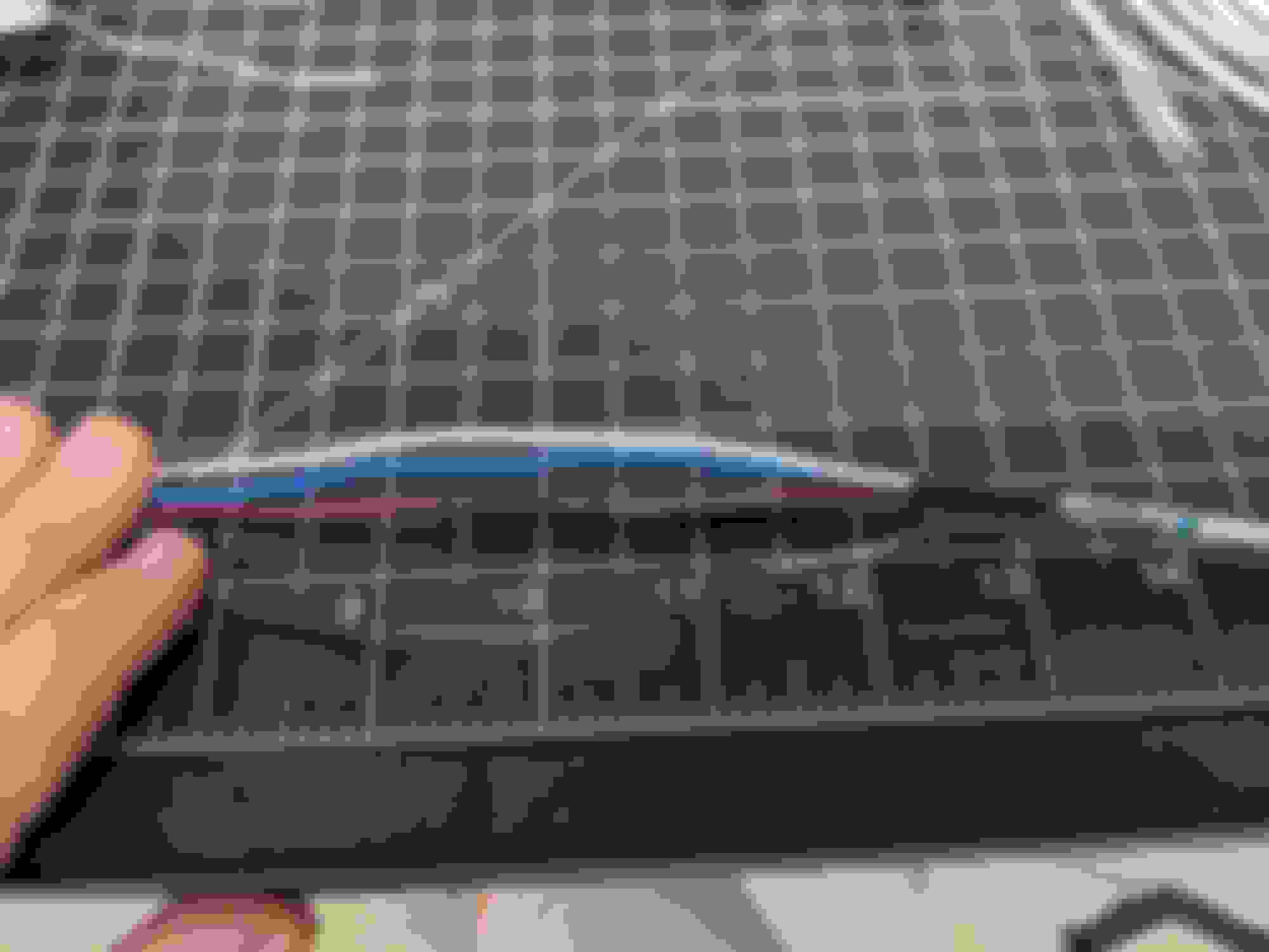
All the shielded wires done:
And then terminate all the shield grounds into a single wire using an M6 ring terminal at the other end, bent 90 degrees.
Then it becomes a bit more routine: measure, route, cut, terminate, repeat. I started with 2A, which ends up at the OMP, and am going in order, 2B (already done as a shielded wire for the AFM), 2C, etc. I've got a few more routed and finished this morning up here:
I'm leaving about six inches of extra wire at the connector end. While not doing a true concentric twist, there will be a little bit of wrap around like the stock harness utilizes.
I forgot to mention, I did a continuity test between the ring terminal and the other end of each shielded wire to confirm each wire will be properly grounded when the harness is installed. I will be doing several continuity checks along the way, as there are several more splices that I will want a double check on.
Which of the heat shrink solder brand did you use? Those look very useful for terminating shield grounds compared to the crimp splice.
I believe these are Raychem brand, which is really just Tyco/TE Connectivity. They came from ProWire, mixed in with the shielded cable. There are various sizes and some have leads and some don't. They can also be found at other places like RaceSpec, Mouser, and probably Digi-Key.
I am done with what I would like to think of as Phase 1. All of the wires coming from the ECU have been run, with the exception of 3A, 3B, and 3C. These are the grounds. For everything - sensors, solenoids, injectors, and engine. That's going to be quite the route and has multiple splices. Everything so far was very straightforward, only one that required some thought was the +5 volt reference for the narrow and full range TPS, OMP, AFM, and pressure sensor.
After the grounds, I will tidy up the short section from the ECU to the breakout for X-10 and X-11, and I may go ahead and wrap that. Then it's the wires for X-10 and X-11, mostly consisting of the wiper motor and cruise control actuator functions. More wrap and also the firewall grommet. Then more wrap and eventually termination of each connector. I've left a lot of extra wire just in case!
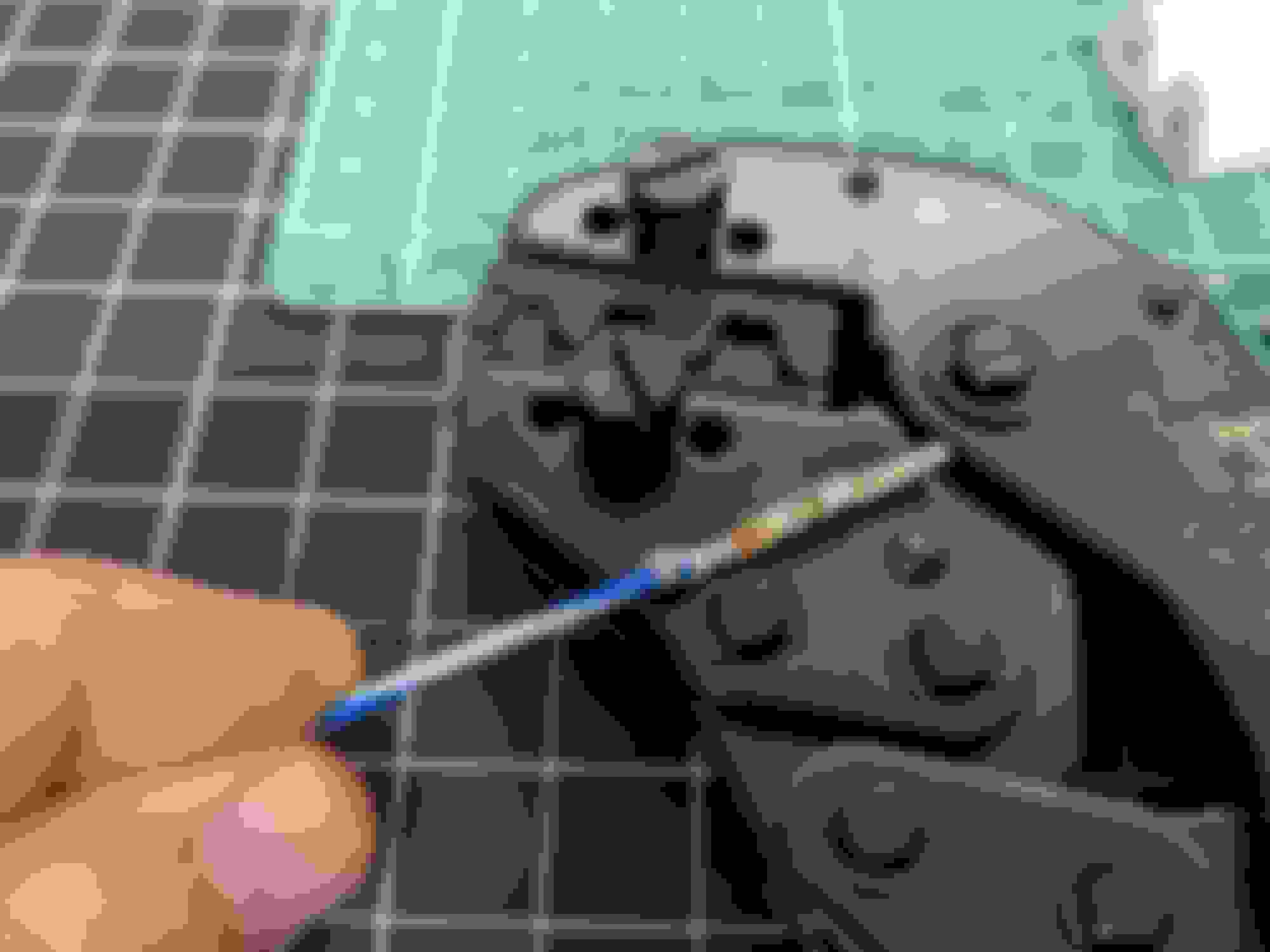
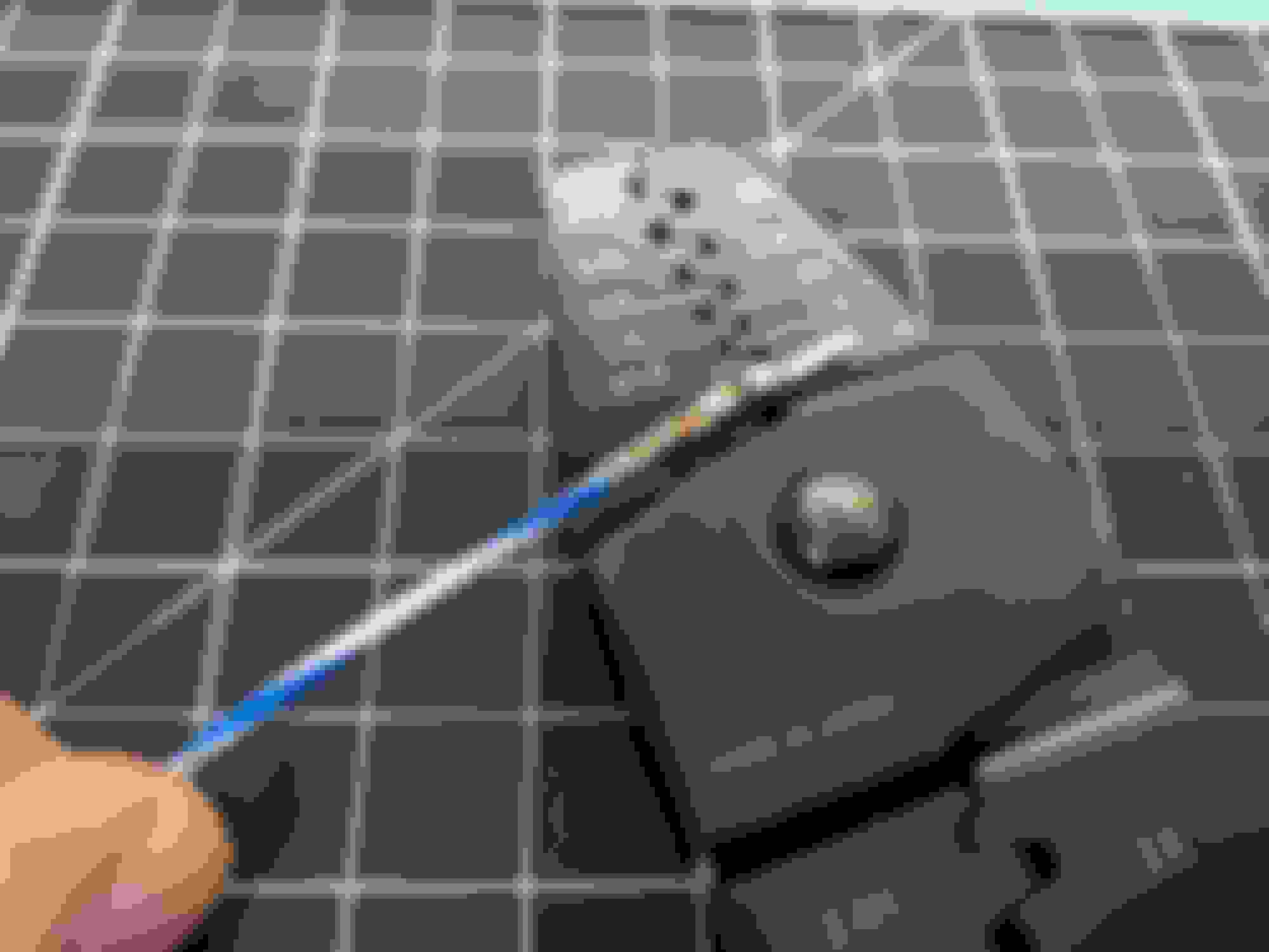
For the crimps at the ECU, I have been using the Hozan crimper. There terminals are much too small for the dies I have for the ratcheting crimpers. I have found for the small terminals that 1.7L works well for the conductor and 2.0H for the insulation. This is slightly against what Ballenger lists in their table, but these are some tiny terminals. Extreme care needs to be taken to not bend the terminal. If you go at it full force, you will deform the terminal and it may not fit in the connector.
Also, I eventually decided to eliminate the solenoid connector for what is identified as Pressure Regulator Control No. 2. It is not mentioned at all in my FSM, was not hooked up on my vehicle, and while in the wiring diagram, is not listed on the ECU pinout table. This was supposed to be terminal 2D at connector B2-23.


 .
.