
please help me get my tachometer working

please help me get my tachometer working
i haven't had my factory tach working for a long tome and im tired of it so im going to fix it..the car has been extensively modified as for the wiring. i scrapped the engine harness and installed a microtech ecu. although from what ive read the engine harness dosen't have anything to do with the tach but what about the dash plugs that went to the factory ecu? could they have anything to do with it? i think the factory tach signal comes out of the trailing coil correct? if that wire is connected where is the next place to look? also where does the trailing coil tach wire go to from there? Would the next step be replacing the cluster?
You can run a jumper wire from the primary coil to a wire that is by the trailing coils and it goes directly to the tach, but in my car it made it read fast a couple hundred rpm.
Thats one way to get the tach back and see if its good, but to do it properly, and by that I mean the stock way, look at the fsm wiring diagrams, even the ones in the Haynes manual are good.
At the moment I cant recall weather the trailing plug signal wire goes to the stock ecu then to the tach or to the tach and then to the stock ecu.
 [/IMG]
 [/IMG]


yeah thats where i got that...downloaded from rx7city.com i dont know why that page is cut off and i cant find any better diagrams of where the wire leaves the coil
Trending Topics
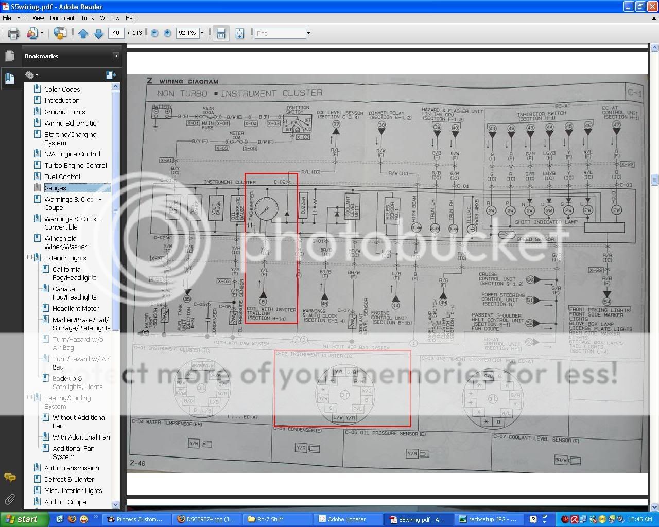
The wiring for the tach from the factory is a yellow /w blue stripe that runs directly to the back of the cluster. It should be coming from the negative on the trailing coil.
I'm also trying to get my factory tach working and have replaced my gauge cluster 3 times now with the same results. I think it may have to do with the 1st gen ignition system.
See my pics attached for more info. I have the pages that are cut off for you.
I'm also trying to get my factory tach working and have replaced my gauge cluster 3 times now with the same results. I think it may have to do with the 1st gen ignition system.
See my pics attached for more info. I have the pages that are cut off for you.
thanks for the diagram..im going to see if that wire is connected. is there any way to check voltage or anything on that wire to see if it is outputting correctly?
The tach signal does come from that yellow/blue wire from the trailing coil. When I put my microtech in I made the mistake of cutting that wire instead of splicing into it - guess what, the tach stopped working! I'd bet this is a common mistake. If the microtech loom was spliced into the Coil loom at the trailing coil, have a look to see if that yellow/ blue wire has been cut completely. If it has, reconnect it!
If that's not the issue, you'll need to take the cluster out and unplug the trailing coil. Check to see if there is continuity between the coil end of the wire and the gauge end of the wire. If there isn't, then you need to find the break in the wire and repair it, or simply run a new wire. If there is continuity, then one of the things on either end (gauge / coil) isn't working.
Give it a try!

Rotary Freak
Joined: Jul 2008
Posts: 1,660
Likes: 2
From: FORT WORTH TEXAS
What is firing your trail coil assy's? The MicrTech or???? Stock ECU?
Have you ever posted this problem on the MicroTech forum?
The trail coil/ignitor has to actually be firing for the tach to work. Just FYI.
The voltage output on the yellow/blue wire is considerably lower than 12vdc if memory serves.
Have you ever posted this problem on the MicroTech forum?
The trail coil/ignitor has to actually be firing for the tach to work. Just FYI.
The voltage output on the yellow/blue wire is considerably lower than 12vdc if memory serves.
its been a while but i finally had a chacne to dig into this issue and try to fix it..hailers2 to my knowledge, the microtech only gives the signal to the coil. not sure if thats what you mean.. anyways today i took a look at the coil wires and what i found was a single barrel connector that was yellow with blue stripe which according to the fsm i think its the test connector. then i found another yellow with blue stripe in a 4 pin connector that wasent connected to anything, so im assuming that is the tach wire i want correct? the problem is, there is NOT a yellow/blue wire coming out of the coil?? so which color wire goes to the yellow/blue tach signal? what i did is found a black or gray wire that was coming out of the coil that wasnt connected to anything, i jumped that to the yellow/blue wire in the four pin connector and the tach started working! but when i set the coil assembly back in the bracket the tach stopped working, now apparently the bracket grounds the coil, but i see a tiny spark when i rub the coil bracket to the ground (chassis bracket) and that stops the tach..whats going on here?? same thing happens when jumping that wire to the test connector barrel connector, i even ran the black or gray wire directly to the pin on the cluster and had the same problem..
stock ignition but i am running a microtech stand alone so i spliced wires to go to the ecu..but this dosent explain why there is no yellow/blue wire coming out of the coil..i found the guage side of the yellow/blue wire but there isnt one coming out of the coil??
Rotary Freak
Joined: Jul 2008
Posts: 1,660
Likes: 2
From: FORT WORTH TEXAS
The ground for the internals of the Trail and Lead coil ignitors is the metal base of the ignitor assy mating to the car chassis. IF the ignitor isn't bolted to the chassis the trail/lead coils won't fire/work. That's why you see sparking when the key is ON and either coil/ignitor assy is removed or unbolted from the car chassis. Normal as apple pie.
The Yellow/Blue wire is a part of the FRONT harness, not attached to the trail coil. It's in a black bullet connector next to the stock trail coil assy. The white elect plugs attached to the trail coil/ignitor assy are a part of the FRONT harness also. If the black bullet connector with the Y/L wire is missing, some fool cut it off or put it to gnd or?????
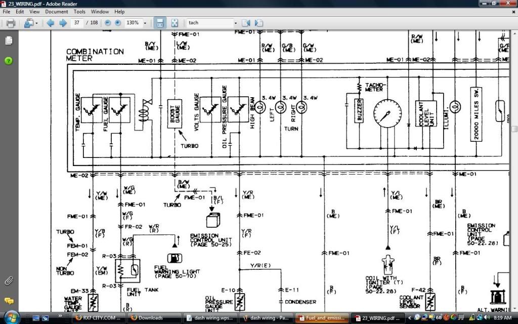
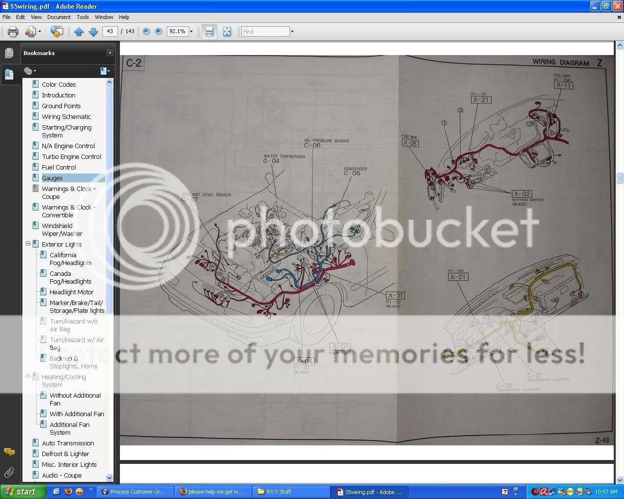
The better half of the FRONT harness is shown in one of the jpgs above and is colored in RED. The ENGINE harness in the same jpg is colored BLUE. The EM harness on the engine is colored black/white.
The jpg in post #4 shows the Y/L wire in the Front harness going to a connector called FME-01 (Front harness to Meter harness) then to the instrument cluster. The next page in the free online FSM wiring diagrams shows the location of FME-01.
The Yellow/Blue wire is a part of the FRONT harness, not attached to the trail coil. It's in a black bullet connector next to the stock trail coil assy. The white elect plugs attached to the trail coil/ignitor assy are a part of the FRONT harness also. If the black bullet connector with the Y/L wire is missing, some fool cut it off or put it to gnd or?????
The better half of the FRONT harness is shown in one of the jpgs above and is colored in RED. The ENGINE harness in the same jpg is colored BLUE. The EM harness on the engine is colored black/white.
The jpg in post #4 shows the Y/L wire in the Front harness going to a connector called FME-01 (Front harness to Meter harness) then to the instrument cluster. The next page in the free online FSM wiring diagrams shows the location of FME-01.
thats the problem..there are no connectors coming off the coil, the wires are all soldered to the microtech harness...so i have 3 signal wires attached to the microtech harness, then i have the 12v ignition connected from coil to the body harness like factory.. but then that only leaves one other wire coming out of the coil, its a black or gray wire, its hard to tell but it looks like a faded black wire, then i can see on the body harness the yellow/blue testing barrel connector, also i see a 4 pin connector on the body harness thats just sitting there not connected to anything, in that 4 pin connector there is a yellow/blue wire, so i connected that to the faded black wire coming out of coil, and the tach started working when the coil wasnt bolted down (grounded) but as soon as i bolted the coil down the tach stopped working..so is that black wire coming out of the coil, the signal wire that is suppose to be connected to that yellow/blue wire in the 4 pin plug?
Full Member
Joined: Mar 2009
Posts: 74
Likes: 0
From: reading,pa
[QUOTE=13bturbofc; but as soon as i bolted the coil down the tach stopped working..?[/QUOTE]
exctally u need to replace your pick up coil and plus the trail coil... this not an wiring or hanress problem.. i had the same problem.. i had to replace the pick up coil and trail.
exctally u need to replace your pick up coil and plus the trail coil... this not an wiring or hanress problem.. i had the same problem.. i had to replace the pick up coil and trail.
Rotary Freak
Joined: Jul 2008
Posts: 1,660
Likes: 2
From: FORT WORTH TEXAS
Well do what BLUE 88 said I suppose.
There were two plugs on the trail coil assy stock. One was two wire and both wires black/yellow.
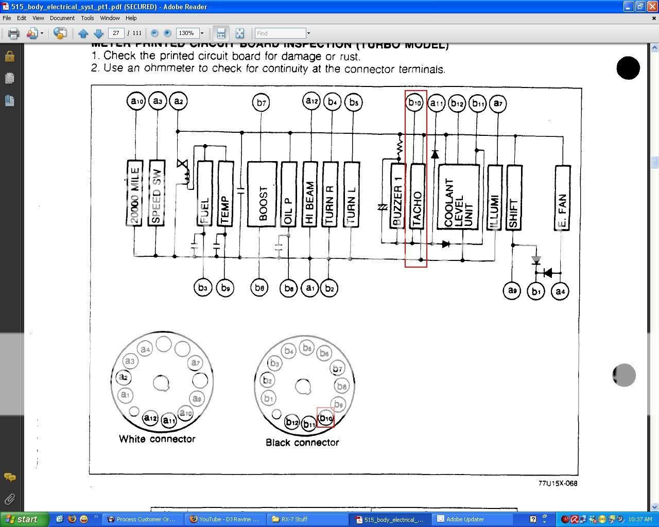
The other plug was four wires of the colors shown in the third jpg attached. FYI the plugs are viewed from the wire side of the plug.
The first two jpg show/tell what each wire does in that plug. Three go to the ECU to pins 1M, 1U, 1X. The fourth wire goes to the tach and also the black single wire bullet connector. Its color is Y/L.
Evidently you want the color of the wires on the ignitor assys pigtail wires. NOT shown in the FSM. After I pull weeds in the backyard I might show the colors of those wires vs the ones that were in the original trail coil assy plug.
There were two plugs on the trail coil assy stock. One was two wire and both wires black/yellow.
The other plug was four wires of the colors shown in the third jpg attached. FYI the plugs are viewed from the wire side of the plug.
The first two jpg show/tell what each wire does in that plug. Three go to the ECU to pins 1M, 1U, 1X. The fourth wire goes to the tach and also the black single wire bullet connector. Its color is Y/L.
Evidently you want the color of the wires on the ignitor assys pigtail wires. NOT shown in the FSM. After I pull weeds in the backyard I might show the colors of those wires vs the ones that were in the original trail coil assy plug.
Rotary Freak
Joined: Jul 2008
Posts: 1,660
Likes: 2
From: FORT WORTH TEXAS
The red and the white wire are in the top of the white plug where the plugs locking device is. The jpg of the half of the plug that connects to the one in this picture also has the locking device on top. So match the wires in the other jpg of the white plug on the Front harness with the white plug on the coil assy that you see in the attached picture.
Rotary Freak
Joined: Jul 2008
Posts: 1,660
Likes: 2
From: FORT WORTH TEXAS
Or the BLACK(dark grey) wire on the ignitor pigtail goes to the Blue/Red wire on the Front harness side of the plug. The White wire on the pigtail goes to the Brown/Yellow wire on the Front harness side of the plug........the Yellow wire on the pigtail goes to the Yellow/Blue wire on the Front harness side of the plug..........the Red wire on the pigtail goes to the Blue/Yellow wire on the harness side of the plug.
So it's the BLACK (or dark grey) wire on the ignitors pigtail that mates with the Y/L wire on the Front harness side of the plug and that wire goes to the tach and also the black bullet connector near the Trail coil assy.
So it's the BLACK (or dark grey) wire on the ignitors pigtail that mates with the Y/L wire on the Front harness side of the plug and that wire goes to the tach and also the black bullet connector near the Trail coil assy.
awesome, thanks for taking the time to dig up all that info hailers..and i did have the correct wire on the ignitor then...its the black wire on the coil that goes to tach signal..i even tried wiring that black wire directly to the back of the cluster and had the same issue, tach worked until i bolted /grounded the coil by bolting on the chassis bracket..so it looks like i need a new coil assembly.like blue88 said..but what do you mean by replace pick up coil and trailing coil? what is the pick up coil?
Rotary Freak
Joined: Jul 2008
Posts: 1,660
Likes: 2
From: FORT WORTH TEXAS
I fucked up. Too hot in Tx and too busy. I took a jpg of the trail coil connected to the harness. Things should be as follows.
Yellow wire on the ignitor assy goes to Y/L on the front harness. That is the tach wire and the wire to the bullet connector (which isn't black but either white or clear in color.
White wire on the ignitor goes to the BrW wire on the front harness.
Black wire on the ignitor goes to the L/R wire on the front harness.
Red wire on the ignitor goes to the L/Y wire on the front harness.
So it's the yellow wire on the ignitor that is the tach player. I looked at two seperate cars Jpgs attached.