
low vac at idle but high compression

Thread Starter
Joined: Jul 2003
Posts: 1,248
Likes: 0
From: Prosser Washington
low vac at idle but high compression
ok last night i was replacing my turbo, i got done sarted it up and it didnt run for ****. turns out one of the injector clips fell off, wich i didnt know so i did a comp check to shee how it wasdoing. in the front i had 120+ in the rear i had 110+. after seeing those neumbers i knew she was still in good shape. well ever since i have had the car the vacuum has always been low. its idles at like 13 to 14. i figured it was a vac leak so i replaced the LIM gasket. still no change. any input. the car runs really well. so far with just intake and exhaust and fuel mods ive ran a 13.50 at 104. any input would be greatly appreciated
btw its an 89 turbo II with a jdm motor
btw its an 89 turbo II with a jdm motor
Joined: Feb 2001
Posts: 29,798
Likes: 128
From: London, Ontario, Canada
Vacuum leaks can come from a lot of places. You need to check all the vacuum hoses (just replace them) as well as the common areas like the TID, rubber hoses at the turbo and intercooler, etc.
Thread Starter
Joined: Jul 2003
Posts: 1,248
Likes: 0
From: Prosser Washington
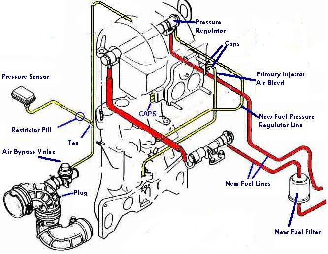
actually that is the wierd thing i just redid my vac system too. i hooked it up like the simplified vac diagram in the link to the fsm i found. i also just put in a trust 3 row fmic and new 3" TID. what should my vac be with those kind of compression numbers?. i have the FPR to the bottom back nipple. the oil injectors to the middle. and on the top vac nipple it is hooked to the vac line that goes inbetween the two oil injectors on the housings. than i have the airl bleeds (i think that is what its called hooked from one to the other than from the other side to the LIM on the back to the firewall. it is a bigger nipple. any ideas?
Thread Starter
Joined: Jul 2003
Posts: 1,248
Likes: 0
From: Prosser Washington
ill check the ignition timing tonight.. last time i checked it, it was right at spec. i dont see how i could have an intake leak. i just replaced the intake gasket and use a lil bit of hi temp rtv around the intake poorts to make sure that i sealed it up really well.
Trending Topics

easy way to check for vac leaks...
get a bottle of some flammable gas. butane works good, such as what you would refill a lighter with.
go around the intake manifold and surrounding area spraying the gas around. if there is a leak, the engine speed will change (increase usually) when the gas is sprayed over it.
get a bottle of some flammable gas. butane works good, such as what you would refill a lighter with.
go around the intake manifold and surrounding area spraying the gas around. if there is a leak, the engine speed will change (increase usually) when the gas is sprayed over it.
Thread Starter
Joined: Jul 2003
Posts: 1,248
Likes: 0
From: Prosser Washington
ill take a look in the fsm.. i have no complaints about how it runs i just think its kinda funny to have that low of vacuum and that good of compression.
Thread Starter
Joined: Jul 2003
Posts: 1,248
Likes: 0
From: Prosser Washington
RETed.. by my vac diagram i posted do you see anything wrong with it?? did i hoook it up wrong.. i also have small sip ties areound all o fthe vacuum nipples to tighten them up.

Lives on the Forum
Joined: Feb 2001
Posts: 26,664
Likes: 23
From: n
Originally Posted by mort2002
RETed.. by my vac diagram i posted do you see anything wrong with it?? did i hoook it up wrong.. i also have small sip ties areound all o fthe vacuum nipples to tighten them up.
I don't think the other two matter, but the FPR has to see a vacuum source when idling - there is only one fitting back there that does that.
Else, everything else looks alright.
About the zip ties on the vacuum hoses...
This is not necessarily a good thing.
If you tighten it down really tight, you actually create a "nook" which can cause a leak.
This is especially true with silicone hose.
Metal spring clamps would be best, but they are not always easy to find, especially in really small sizes (under 1/2").
-Ted
Boost in..Apex seals out.
Joined: Nov 2003
Posts: 1,931
Likes: 0
From: Maryland, 21794
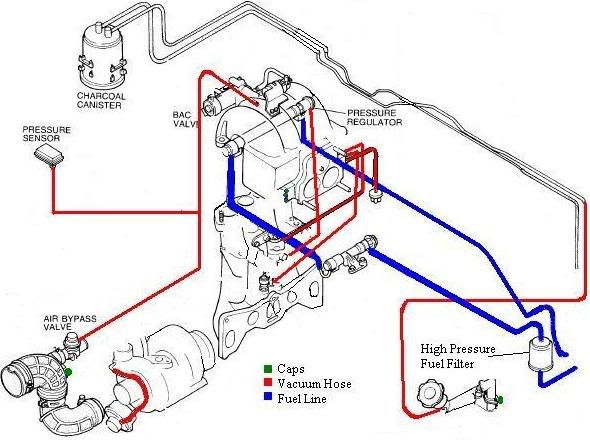
Dude, that FSM diagram is INSANELY hard to read. Here..use this one. It's my modified version of Karack's (I think), could've been NZConvertible...
Just use your imagination as to where you should add in all your other lines (like OMP related lines).
Just use your imagination as to where you should add in all your other lines (like OMP related lines).
Thread Starter
Joined: Jul 2003
Posts: 1,248
Likes: 0
From: Prosser Washington
th only thing that sucks is that the diagram you gave me is for an S4 so it doenst have the upper air bleed. i am going to go though and double check all of my block off plates and make sure they are all sealed up good. any more advice??
Lives on the Forum
Joined: Feb 2001
Posts: 26,664
Likes: 23
From: n
Just remember, if you keep the bleed valve fittings (primaries goes in between the two oil injectors on the LIM, and the secondary ones runs across the LIM right next to the secondary fuel injectors themselves), these need to see a fitting BEFORE the throttle body.
In fact, if you want to simplify it even further, just cap the secondary ones and worry about the single primary one.
The secondaries really don't need this air bleed crap!
-Ted
In fact, if you want to simplify it even further, just cap the secondary ones and worry about the single primary one.
The secondaries really don't need this air bleed crap!
-Ted
Thread Starter
Joined: Jul 2003
Posts: 1,248
Likes: 0
From: Prosser Washington
do you kinda have a diagram of what you are tlaking about.. maybe just edit my diagram i posted or something.. i would really appreciate .. and i appreciate all the help already RETed!

Haven't we ALL heard this
Joined: Mar 2001
Posts: 3,948
Likes: 1
From: Indiana
Ok an easy way to check for vacuum leaks does not start with a running engine and flamable gas.
The best way to check for leaks is this. Go to home depot in the plumbing section and buy a rubber end cap (they already have hose clamps on them) and buy one big enough to fit on the end of your TID where the filter goes.
Remove your filter and snug the rubber end cap on it. Punch a hole in it...then get an air hose and pressurize your intake to like 20psi. If you have a leak...your going to hear it.
James
Thread Starter
Joined: Jul 2003
Posts: 1,248
Likes: 0
From: Prosser Washington
RETed: if you can get me a modified pic this weekend, thats ok, i dont drive my car daily. thanks a bunch
Wankel7: do you have like a pic of what you made. i was thinking fo doing the same thing but i always wondered where the pressure goes after it enters the intake.. does it just compress onto the rotors... thanks!
Wankel7: do you have like a pic of what you made. i was thinking fo doing the same thing but i always wondered where the pressure goes after it enters the intake.. does it just compress onto the rotors... thanks!
Haven't we ALL heard this
Joined: Mar 2001
Posts: 3,948
Likes: 1
From: Indiana
Originally Posted by mort2002
RETed: if you can get me a modified pic this weekend, thats ok, i dont drive my car daily. thanks a bunch
Wankel7: do you have like a pic of what you made. i was thinking fo doing the same thing but i always wondered where the pressure goes after it enters the intake.. does it just compress onto the rotors... thanks!
Wankel7: do you have like a pic of what you made. i was thinking fo doing the same thing but i always wondered where the pressure goes after it enters the intake.. does it just compress onto the rotors... thanks!
I guess it depends where the rotor is in the cycle but yeah i guess it would. No big deal though...not like you can detonate when the car isnt running

James
Lives on the Forum
Joined: Feb 2001
Posts: 26,664
Likes: 23
From: n
Only problem with the above diagram is that the "PCV" needs to be vented.
It looks like it's all plugged up or trying to be rerouted back into the gas tank?
You're going to have problems trying to fill gas if this is the case.
I try to keep the whole PCV system, since the turbo smokes like crazy if you don't have some kinda PCV relief.
-Ted
It looks like it's all plugged up or trying to be rerouted back into the gas tank?
You're going to have problems trying to fill gas if this is the case.
I try to keep the whole PCV system, since the turbo smokes like crazy if you don't have some kinda PCV relief.
-Ted
Thread Starter
Joined: Jul 2003
Posts: 1,248
Likes: 0
From: Prosser Washington
ok with the diagram... what about the bigger nipple on the LIM facing the fire wall. iver never seen anything about it, in any drawing.. as for the pcv; i just have the crank nipple and the filler neck nipple going to a tee with a filter on it?? does that sound good? any thiughts on eliminating the 2nd dait air bleeds and the big nipple on the back? thanks
Rob
BTW i thought the oil metering lines went to the middle vac nipple on the back no the bottom one?? wich one is right?
Rob
BTW i thought the oil metering lines went to the middle vac nipple on the back no the bottom one?? wich one is right?
Last edited by mort2002; Aug 11, 2006 at 10:02 AM.