Josh's Build Thread

 08-03-12, 02:03 AM
#177
Oil flows from oil filter thru the dowel pins into front iron, then it splits between banjo bolt for turbo oil line, the hole you drilled and rest goes to front stationary gear bearing.
If you drilled and had some shawings to get inside, then used compressed air expecting they will get ouside by banjo bolt, they could have as well went other way > towards stationary gear bearing....
If you drilled and had some shawings to get inside, then used compressed air expecting they will get ouside by banjo bolt, they could have as well went other way > towards stationary gear bearing....
08-04-12, 10:26 AM
#179
Day 64: Today I got the front cover put back on. I also finished the last little bit of touch up sanding on the body. After that I started working on the fridge I got, to harvest the compressor off of for vacuum bagging the second set of body parts. I am using the rest of the fridge to store paint in...it's a good way to keep dust and over spray off the containers. Then I started mocking up the v-mount setup. Here's how I did it:
I started by putting in the factory radiator and I used the hoses to determine where the motor's boundaries were and to determine hood clearance.

I used strings to mark the boundaries so I could mock everything up.

I did some CAD (Card-board Aided Design) to make the IC core I was considering using

Then I made a mock up FD radiator and mounted it in the engine bay

I think this set up should work. Here's some pics from different angles.
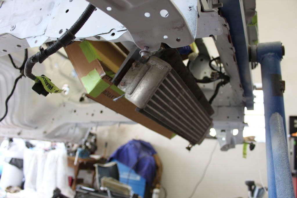


Now, there's a few reasons for using the FD radiator. FDs in stock form run more boost and more power than we do. And their typical bolt ons usually see more power than we do. So I figure if I use FD fans with an aftermarket FD radiator, I should be just fine. Plus, it has the advantage of being shorter so the angles are more conducive to the v-mount setup. If anyone has any input on this idea, I'd appreciate it. I'm just trying to work with what I have.
Here's a pic comparing the two factory radiators

I started by putting in the factory radiator and I used the hoses to determine where the motor's boundaries were and to determine hood clearance.
I used strings to mark the boundaries so I could mock everything up.
I did some CAD (Card-board Aided Design) to make the IC core I was considering using
Then I made a mock up FD radiator and mounted it in the engine bay
I think this set up should work. Here's some pics from different angles.
Now, there's a few reasons for using the FD radiator. FDs in stock form run more boost and more power than we do. And their typical bolt ons usually see more power than we do. So I figure if I use FD fans with an aftermarket FD radiator, I should be just fine. Plus, it has the advantage of being shorter so the angles are more conducive to the v-mount setup. If anyone has any input on this idea, I'd appreciate it. I'm just trying to work with what I have.
Here's a pic comparing the two factory radiators
08-04-12, 10:58 AM
#180
Passion for Racing
Join Date: Aug 2010
Location: Crown Point, Indiana
Posts: 1,066
Likes: 0
Received 2 Likes
on
2 Posts
good start, but the flow through the rad will not be good because youre asking the air to go through the oil cooler, up through the rad and then through the IC. The problem isn't getting air to flow good between the three, it's getting it through the rad in your design. The way you have it set up is sort of a box design that the air can flow through, but the rad happens to be a wall in that box, not a part in the box for air to flow through. I would try hard to mount the rad as close to stock position as you can, and build yourself a nice sealed cavity for he air to flow through and out.
Sory if that is hard to make sense of, it is hard to try and explain things wthout a diagram.
Sory if that is hard to make sense of, it is hard to try and explain things wthout a diagram.
08-04-12, 11:14 AM
#181
I should have included the fact that there will be a significant amount of duct work done. I just didn't mock the ducts up yet because I don't have a front bumper done yet and I didn't want to obscure the positioning. The ducting will block off the sides and divide the flow so that the rad/oil cooler have their own duct and the IC has its own. IIRC, the ideal duct opening for proper air flow is 1/4-1/3 the area of the heat exchanger.
Given the cores surface area of 180cm2, I only need a 60cm2 duct inlet...which is quite easy with the FC2000 bumper.
Hope all that makes sense. I'll mock up the ducting as best I can and post more pics
Given the cores surface area of 180cm2, I only need a 60cm2 duct inlet...which is quite easy with the FC2000 bumper.
Hope all that makes sense. I'll mock up the ducting as best I can and post more pics
08-04-12, 11:44 AM
#182
Sorry, dropped a zero there. It's 1800cm2 total area for each core, which means I need a duct opening area of 540cm2 for the IC and another of the same size for the rad/oil cooler. Basically I just have to split the opening in half on the FC2000, that will make two opening that are roughly 600cm2. That should ensure there is a sufficient pressure differential to pull the air through both IC and radiator.


 08-05-12, 10:14 AM
#185
If you are going to leave the oil cooler in the stock location, consider raising the angle on the IC core so that it is more horizontal. This will allow you to move the Radiator up so that it is unobstructed by the oil cooler. Even with duct work that little pocket below the top of the oil cooler will not see optimial airflow as it will have no incentive to make the 90* required to flow through the bottom 2" or so of your radiator.
Edit:
I don't have any pics from the side to illustrate what I'm talking about, but this gives you an idea. The difference of course being that you would have less overhang past the rad support because you have an FD rad which would work much better than the FC based koyo I used.

More pics here: https://www.rx7club.com/build-thread...-999774/page3/
This would be preferable because you are restricting space on the front end, where you only need 1/4 - 1/3 of the surface area of the core anyway. This will also make for an easier time creating effective duct work.
Edit:
I don't have any pics from the side to illustrate what I'm talking about, but this gives you an idea. The difference of course being that you would have less overhang past the rad support because you have an FD rad which would work much better than the FC based koyo I used.
More pics here: https://www.rx7club.com/build-thread...-999774/page3/
This would be preferable because you are restricting space on the front end, where you only need 1/4 - 1/3 of the surface area of the core anyway. This will also make for an easier time creating effective duct work.
08-05-12, 11:15 AM
#186
It looks like you're running a much tighter V. I don't think I need to be quite as tight because of the shorter FD radiator and the larger bumper opening of the FC2000 bumper.
I wish you had more pics. Maybe a better bet for me would be to adjust the positioning of the oil cooler. Maybe to where it fills the entire opening that would lead to the radiator side of the ducting. It may warm the air a little more, but I doubt it will make much difference.
Edit: After looking at more of your pics, my bumper opening is quite a bit lower than yours, which is why I can run a wider 'V'.
08-05-12, 05:45 PM
#187
Unfortunately, the only way to really take advantage of that extra bumper area is to cut out the front support and relocate it. You can run a wider "v" but you will either have to put the rad behind the support which obstructs airflow, or use your current configuration which is similarly undesirable.
Of course, you could also move the rad in front of the support and relocate the oil cooler lower and/or further forward.
Of course, you could also move the rad in front of the support and relocate the oil cooler lower and/or further forward.
08-05-12, 10:16 PM
#188
Which support are you talking about? The round one that the oil cooler bolts to? Or the triangular one in front of that?
The round one I'm not too concerned about moving, just removing brackets. It is in the airflow from the factory and doesn't seem like much of a hindrance since its round. The triangular one should actually line up with the top of the bumper opening, so it can be used to mount ducting.
I suppose I need to get the brackets cut off so I can do a more accurate mock up. Getting the actual IC would help too. I found an aluminum FD v-mount radiator (both inlet and outlet are on the top) that should work well.
08-06-12, 10:07 AM
#189
Finally got a source for my hybrid turbo parts. Here's the supplier in case anyone else wants to use em: Garrett T04 T04E Cosworth Compressor upgrade turbo RS Hybrid A/R 60 57 Trim kit | eBay
Legit parts that are being sold for the intended purpose of upgrading. Not the cheapest solution, but the most convenient for me.
Legit parts that are being sold for the intended purpose of upgrading. Not the cheapest solution, but the most convenient for me.
08-10-12, 01:11 AM
#193
Day 66: Last night I trimmed the excess metal from the front end and rechecked my mock-up...should work very well. I also marked the hood for the cutout for the scoop.
Today I'll cut out the hood, finish the rear end bushings and get ready for round two with the fiberglass. I'm also going to try and get my brake hard lines "ordered" so I can pick them up on Monday. The hard lines are really the only thing left to do before I can take the car off the rotisserie.
Today I'll cut out the hood, finish the rear end bushings and get ready for round two with the fiberglass. I'm also going to try and get my brake hard lines "ordered" so I can pick them up on Monday. The hard lines are really the only thing left to do before I can take the car off the rotisserie.

 08-10-12, 08:44 PM
#196
I ended up choosing to go with side mount oil coolers for my vmount setup... but my second idea was to toss the oil cooler inside the bumper core. Cut a hole in it for flow, and duct it up and out, in front of the intercooler.
Your build is coming along very nicely.
Your build is coming along very nicely.
08-11-12, 01:15 AM
#197
Yeah, I thought the same thing, lol. But it's not all open and it's just big enough to stay in the big low pressure zone, so should do a good job of sucking all the air through the heat exchangers and any left over heat in the engine bay.
08-11-12, 02:07 PM
#198
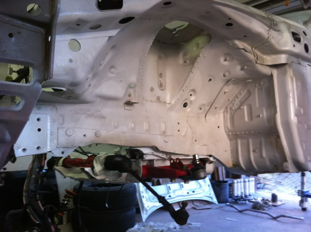
Day 68: Today I painted quite a few pieces (brackets, etc). I mounted the rest of the front suspension with the exception of the left spindle, because I'm waiting for a new one to come in the mail. I also test fit my Sparco seat and 4pt harness. I ordered my front caliper hard lines and a new return-to-center shifter spring from Mazdatrix and my v-mount intercooler core off eBay. I'll need to order some couplers and some pipes, but this should be the last of the major parts I need to order. I had to delay fiberglass until tomorrow.


08-12-12, 03:06 PM
#200
Day 69: Today I finally got the front bumper fiberglassed, with much help from a friend. I learned a lot today about molding. I also finished painting some rear suspension parts and installed some brackets in the engine bay. Tomorrow I'll finish layering on some more fiberglass on the front bumper and it'll be done. No pics, maybe tomorrow if I get the bumper de-molded. I'll definitely be doing another set of fenders and a hood scoop.