
Fuel pump connection pinout?

Fuel pump connection pinout?
Car is stock S5 N/A.
S4 fuel tank/pump/assembly
Dont have a S5 tank or pump assembly right now but do have a S5 pump laying around.
Plug the S4 fuel pump into the harness and the car ran(even tho the colors didn't match up on the harness plug)
Question 1: Is it OK to run my car like this?
Question 2: What pinouts do i need to change for my fuel gauge to work again?
Thanks for any input. - Nick
Sequentially broken
Joined: Apr 2003
Posts: 448
Likes: 1
From: Wisconsin
It should be fine to work as it is, has your fuel level ever worked previously? The details are below:
S5
Two blue/green coming from the FP relay, which are spliced together
W/R goes to the low fuel light in the idiot cluster
W/G goes to the level sender
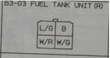
S4
Two blue coming from the FP relay, splice together
W/R goes to the fuel warning light
W/G goes to the sender
Doh, damn editing for the connectors didn't work out so well.
S4 Connector
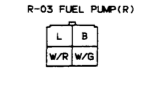
S5 Connector
S5
Two blue/green coming from the FP relay, which are spliced together
W/R goes to the low fuel light in the idiot cluster
W/G goes to the level sender
S4
Two blue coming from the FP relay, splice together
W/R goes to the fuel warning light
W/G goes to the sender
Doh, damn editing for the connectors didn't work out so well.
S4 Connector
S5 Connector
Fuel gauge and low fuel warning light worked with s5 pump/tank. Now the needle is like full when there is low gas and low fuel warning light isnt coming on. Took out fuel pump and even saw it was very very low and gauge and low fuel light dont work.
ok on the s4 pump the red is power, the black is ground, leaving w/r and w/g to be the gas gauge or the low fuel sensor. Its cut off in my copy of the FSM I'll get another copy and get back to you.
Looks like someone beat me to it, I would try switching the bottom two based of what you said about the behavior of the instruments.
Looks like someone beat me to it, I would try switching the bottom two based of what you said about the behavior of the instruments.
Trending Topics
ok on the s4 pump the red is power, the black is ground, leaving w/r and w/g to be the gas gauge or the low fuel sensor. Its cut off in my copy of the FSM I'll get another copy and get back to you.
Looks like someone beat me to it, I would try switching the bottom two based of what you said about the behavior of the instruments.
Looks like someone beat me to it, I would try switching the bottom two based of what you said about the behavior of the instruments.
Sequentially broken
Joined: Apr 2003
Posts: 448
Likes: 1
From: Wisconsin
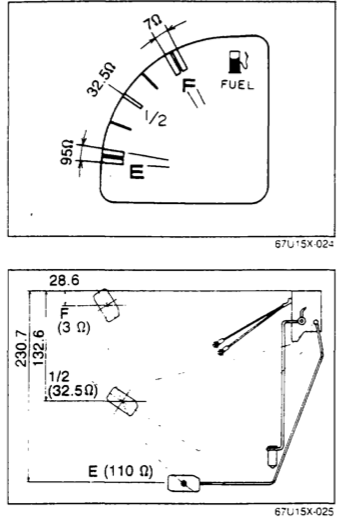
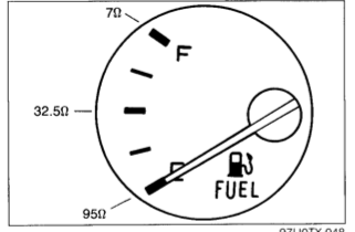
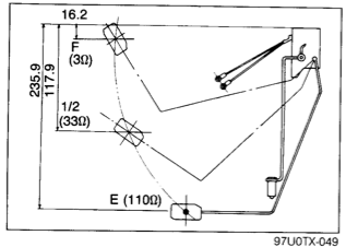
There shouldn't be any difference in the sending units themselves, they return very similar Ohm values, and the gauges display similarly based upon those. I've attatched the FSM diagrams for this as well, so you can check the resistance. To check, just get a multimeter set to ohms, ground the negative lead and connect the other lead to the W/G.
S4
S5
S4
S5
Sequentially broken
Joined: Apr 2003
Posts: 448
Likes: 1
From: Wisconsin
I mentioned that in the post, the W/G wire with the positive lead, and the other is grounded. I don't know how else you'd be able to check without a multimeter other than pulling the unit out by hand and testing the gauge values at the different positions of the swing arm
I mentioned that in the post, the W/G wire with the positive lead, and the other is grounded. I don't know how else you'd be able to check without a multimeter other than pulling the unit out by hand and testing the gauge values at the different positions of the swing arm

Thread
Thread Starter
Forum
Replies
Last Post
trickster
2nd Generation Specific (1986-1992)
25
Jul 1, 2023 04:40 PM
ChrisRX8PR
Single Turbo RX-7's
21
Oct 18, 2015 04:01 PM
KAL797
Test Area 51
0
Aug 11, 2015 03:47 PM