When you click on links to various merchants on this site and make a purchase, this can result in this site earning a commission. Affiliate programs and affiliations include, but are not limited to, the eBay Partner Network.
My headlight switch works as it still lights up the instrument panel but the parking lights don't work. Headlights still works and the RET motor is still functional.
When the headlight switch is OFF. I noticed a drain of over 12V coming from the RET 30 circuit.
I figured this out by putting a DMM between the terminal and battery. The only way to stop the drain is by pulling the 30A fuse from the RET circuit.
What should i do. I have no working parking lights and the RET circuit is draining my battery. Are these two related? is the Parking light on the RET circuit?
It's a different circuit. The retractor fuse sends constant 12 volts to the retractor motor via the White/Green wire which is normal. If your tail lights don't work then check the illumination fuse. The fuse powers the Red/Black wire which powers the side markers, license plate lights, glove box, clock, radio in addition to the tails. If the fuse is good but the Red/Black wire to these items does not have voltage w/the light switch set to the 1st or 2nd position then suspect the switch and or harness for the switch.
So the constant draw from the battery with the ign off from the RET circuit is normal? How does this not kill the battery?
Also, How do I get to these wires? do I have to pull apart my dash? if the fuse is fine and the dash still lights up can I assume the switch is fine and its in the harness somewhere? or can the switch still be the issue?
The dash lights are supplied voltage from the Red/Green wire and not the Red/Black wire but both are powered by the same illumination fuse. If the R/B wire powers the tails and side markers then all you have to do is check the wire at any of these places such that pulling apart the dash is not really necessary. If the dash lights work but not the lights powered by the R/B wire then there is likely a wire/bulb issue going on. The R/B wire coming off the headlight switch runs to connector FC-02 which mates the cluster harness to the front harness and a poor connection could be causing your problem perhaps. The FSM wiring diagram indicates the location of this connector (near the driver kick panel).
The voltage going to the retractor motors is 12 volts but that is not necessarily equivalent to a 12 volt drain as they are two different animals. The drain created is minimal and should not be problematic for the battery unless you never use the car over a prolonged period of time. There are two signal wires to the retractors. One tells the motor to stay down and the other tells the motor to go up and one of the two wires receives voltage at all times (the battery supplies constant voltage to numerous items such as all the interior fuses powered by the Btn fuse and the starter motor also receives constant voltage as well).
the yellow wires are not factory so we could guess all day as to what that relay is for. the parking lamps inop is likely a faulty headlight switch.
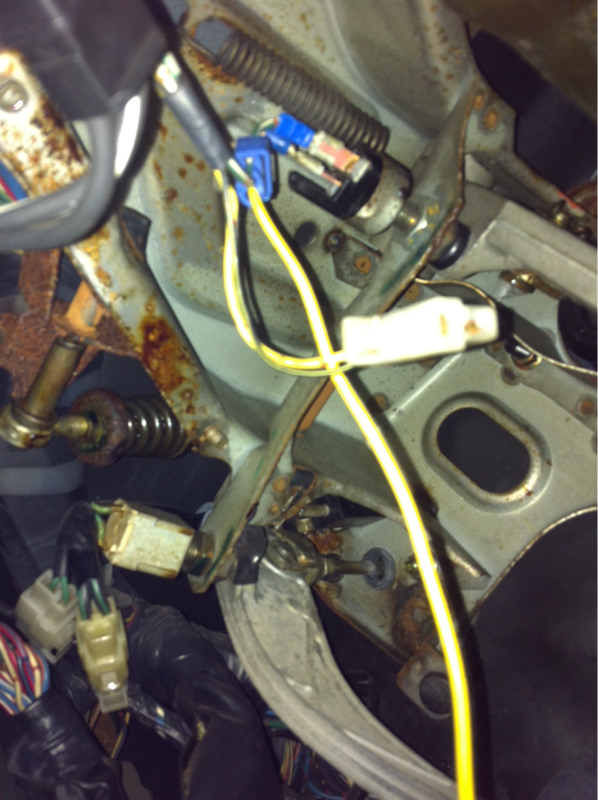
the dangling connector by your feet, i dont recall what that one is for but there should be the other mating connector behind that kick panel. its either for the ECU(flasher and buzzer relay) or front to rear body harness.
you're being totally random, are you looking for a draw or trying to fix a specific issue? if you're still looking for the draw then you will need to find out draw amp numbers and from a specific circuit, not just say you found a draw. you haven't even said how long it takes for the battery to fully discharge so that we have an idea of how large the draw is(which incidentally also doesn't always have to be a draw, dead/dying batteries don't have much reserve and even small normal parasitic draws from the car can run them down overnight).
That relay is not stock so it is anyones' guess as to what it is for.
Go to the front of the car and look in between the battery and the leading coil area(driver's side) to find a round connector about the size of a half a roll of dimes.(also one on the passenger side) ]
They are the connectors for the retractor motors.Pull one at a time and test the circuit for draw.
Also there is a connector on the back of the alternator that is "tee shaped" and that is for the signal to dash (voltage to meter).If that isn't hooked then the gauge will not read.Also it will give you a Light in the Panel telling you something is up.
If you go to the back of the car and expose the plug to the tail lights and you'll find the R/B wire. Again, if the side markers are not working then pull the light housing off of the marker and you'll find the R/B wire. And as suggested if you find FC-02 then that is where the R/B from the cluster harness mates with the front harness. You would check both sides for voltage when the headlight is turned to either position as voltage should be present on both sides. If you have voltage on the R/B wire at the tails and side markers then your problem most likely is the ground wire or the bulbs.
FC-02 has some of the following colored wires on the row w/the least amount of wires; G/W, G/R, R/B, Red/Blue and then open space in this particular order (this is the cluster side of the harness). These wires connect to the front harness and these wire colors are G/B, G/R, R/B, Red/Blue and then open space. So, G/W connects to G/B, G/R to G/R and R/B to R/B and so on.
So all I'm still trying to figure out my parking light issues and I came across these cut wires. Does anybody know what they are for? Someone before me attached a relay to the connector end and the other side is tapped into the wires running to the brake light switch.
Thanks
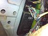
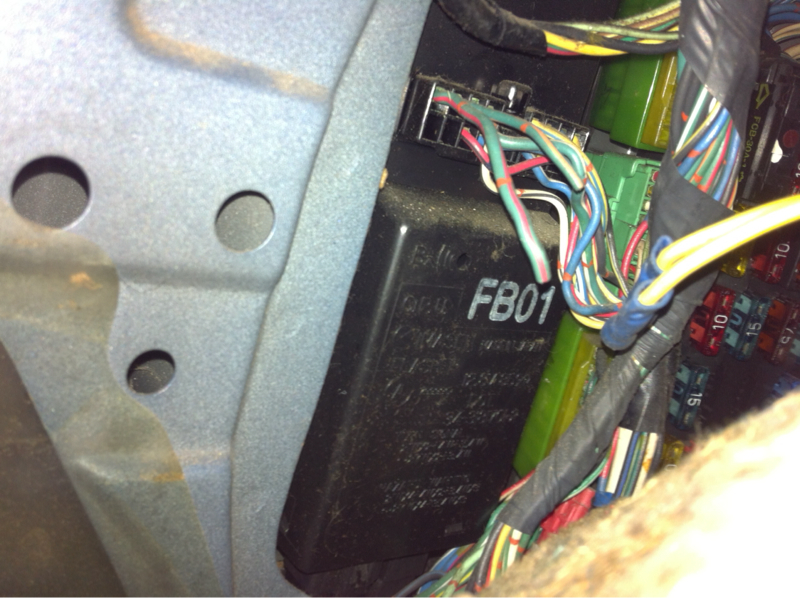
Does anyone know what the fb01 box is and the wires coming off it is cut and ran into a relay which is then tapped into my brake light switch. The two orange/green wire
that box is your flasher/combination and warning relay, i can't see where that green/orange wire goes to in the diagram though, that is plug F-04 with the chopped and hanging wire. also can't see what wires that relay is spliced into, my eyes did't come with auto focus, pan and zoom.
gotta love other people's science experiments.
edit: found it, the green/orange cut wire is for the horn relay. course simply unplugging the relay woulda been easier than cutting the wire.... most likely put in an aftermarket steering wheel which closed the contacts for the horn.
Last edited by RotaryEvolution; Nov 11, 2015 at 08:07 AM.
And the cut Green/Red wire runs to the horns. Are you stating that the Yellow wires are connected to the other end of the G/O and G/R wires and they run to your brake light switch.
FB-01 is the CPU.
Again, you were given enough info in post #9 to help diagnose your tail light/side marker issue.
the brake switch is apparently the control for your relay, but i still cant see what the 2 yellow wires are attached to near the FB01 module, which would explain a bit more what is going on. if it is going to the green/orange... that is your horn relay activation circuit wire.
it appears to just be some high school auto shop prank, but completely unrelated to your other lighting issues unless the power feed to that relay was taken from the lighting power feed wire.
you have 2 choices for the lighting, do as satch said and pull the bulbs and check for power, or switch the headlight switch with one you know works if you have one. i find it highly unlikely it is a grounding issue for both the front and rear harnesses, i tend to lean more on it simply being a faulty headlight switch whenever the parking and dash lights both are inoperative.
Last edited by RotaryEvolution; Nov 11, 2015 at 11:35 AM.
If you look at the 2nd paragraph in post #9 it lists the sequence of wire colors when looking at the very end of FC-02 in the row w/the gap in the middle row. Should be rather straight forward.
Got off work and decided to test the connector hopefully I pulled the correct one. I have a really hard time seeing colors. But I tested this connector third pin in hopefully this is the correct one
. It powers on and off with the switch. But I have no power still at the r/b wire at the tail lamps.
Got off work and decided to test the connector hopefully I pulled the correct one. I have a really hard time seeing colors. But I tested this connector third pin in hopefully this is the correct one
. It powers on and off with the switch. But I have no power still at the r/b wire at the tail lamps.
correct connector, wrong wire. that is R/G. The R/B wire that powers the markers is the wire to the toward the inside closer to the other connector on the far side.
the W/G wire that powers the headlight switch is just to the right of the locking tab on the far side of that connector as well.
There are 2 rows to a connector. There is a row with wires straight across. There is also a row where there is an open space/gap in the row. This is the row you need to look at for there are 4 wires followed by the gap and then 4 more wires. If you are looking at the row with no gap then that is the wrong row. And the 4 wires next to the gap are listed below in the info from post #9.
FC-02 has some of the following colored wires on the row w/the least amount of wires; G/W, G/R, R/B, Red/Blue and then open space in this particular order (this is the cluster side of the harness). These wires connect to the front harness and these wire colors are G/B, G/R, R/B, Red/Blue and then open space. So, G/W connects to G/B, G/R to G/R and R/B to R/B and so on.
Update- I FOUND THE RB wire. I tested it on both sides I have no 12V. I tested the W/G and I see that it does have 12V.
I found that if I jump the wires between the GW to the RB my parking lights will light up.
I also found that the easiest fix is that if if I jump the GB for headlights and the RB on the switch side I can get away with having my parking lights work at night when I turn on the headlights. Is this an okay fix to get me around or will I melt some wires?
Should I purchase a rely and tap it into my headlights so I can have a dedicated power for the RB?
replace the headlight switch and make sure the harness isn't burnt.
you could control it via relays but you will still likely need a switch anyways. tapping into the headlight power isn't a good idea, because if you lose that....


 if the fuse is fine and the dash still lights up can I assume the switch is fine and its in the harness somewhere? or can the switch still be the issue?