
[VIDEO] Freshly rebuilt/ported S5 T2 cutting out/breaking up at high rpm.


Sounds like the coils are firing correctly.
The Leading coils are waste spark with both firing together as you noted and the Trailing alternate.
The wasted Leading spark is in the exhaust stroke.
The main Leading spark would have to be crazy retarded for the wasted Leading spark to happen during the compression stroke as the plug is below the minor axis of the rotor housing. (Leading= Lower)
The Leading plug fires BTDC (Before Top Dead Center) even in its most retarded state, so unless you have the base timing way off at the CAS timing retard under boost is not a problem.
The Trailing plug does indeed fire ATDC (After Top Dead Center) in the rotary, so because of its position above the rotor housing minor axis it cannot be waste spark or it would spark during the compression stroke. (Trailing= Top)
Interesting, I didn't know about that. Just looked up wasted spark. So I'm guessing that the spark will never retard enough to where the apex seal would be past the leading plug, else wise it would ignite early. Unless the timing was already retarded a bit in the first place..
I'm going to try to fire the engine up now using the new leading coil with the old trailing coil since that was the only other result which gave me full spark just to see what happens.
So still having same problem as in the original video with new leading coil. The engine idles extremely smooth and sounds good, I don't think there is a timing issue, but I am going to check with a timing gun anyways tomorrow morning when I borrow one.
Any ideas out there? What should I look or test for? I need to have this car running in the next few days.
Any ideas out there? What should I look or test for? I need to have this car running in the next few days.
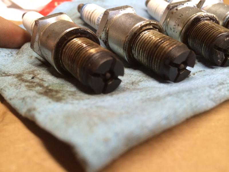
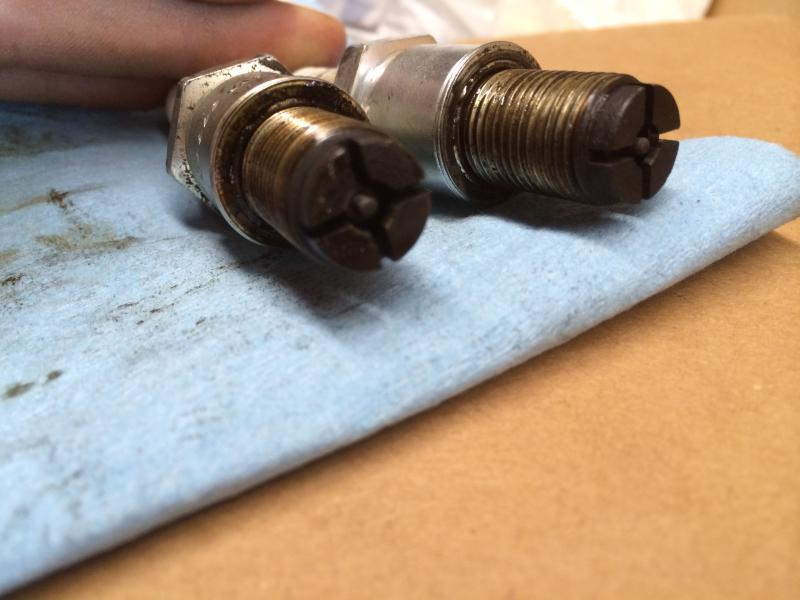

Not an expert as to how the plugs should look like but I thought a light grey color was the best. Yours don't look like that and they actually look like dark black. What does this tell you?
And does your tach work yet?
And does your tach work yet?
And I still have no tach.
The point I was trying to make is what do you think is the cause is for your plugs to look like that?
When was the last time the tach worked? If you wanted to test to see if the tach itself works you could jumper the two bullet connectors at each coil to each other and the lead coil will drive the tach.
When was the last time the tach worked? If you wanted to test to see if the tach itself works you could jumper the two bullet connectors at each coil to each other and the lead coil will drive the tach.
The tach hasn't worked since I put this motor back together. I did try to jumper those when I first had that problem up at the track, but it's worth giving another shot.
OH and I just realized, when I tried that up at the track, I think I had the trailing coil plugged in, but not mounted (grounded) to get to the bullet connector underneath more easily. But I don't think that would make much of a difference?
OH and I just realized, when I tried that up at the track, I think I had the trailing coil plugged in, but not mounted (grounded) to get to the bullet connector underneath more easily. But I don't think that would make much of a difference?
I'm going to first try to use the bad trailing coil I picked up. Should start and run the car since the leading coil works fine. But if the tach works on that, it should tell me I have two bad trailing coils right?
The coil itself won't work if it's not grounded. This is one of the reasons it was suggested earlier to address this. If it meant sanding down the contact points of the fender and mounting bracket then so be it in addition to cleaning the bolt threads. If the coil was not grounded then that could prevent the lead coil signal from passing through the trailing on its way to the tach. And the Yellow/Blue wire of the trailing coil which supplies the tach signal should read close to .6 volts w/key to on if I remember correctly.
And getting back to the plugs, what do you think the cause is for then to be covered in black carbon?
And getting back to the plugs, what do you think the cause is for then to be covered in black carbon?
The coil itself won't work if it's not grounded. This is one of the reasons it was suggested earlier to address this. If it meant sanding down the contact points of the fender and mounting bracket then so be it in addition to cleaning the bolt threads. If the coil was not grounded then that could prevent the lead coil signal from passing through the trailing on its way to the tach. And the Yellow/Blue wire of the trailing coil which supplies the tach signal should read close to .6 volts w/key to on if I remember correctly.
These plugs have been in the motor for probably short of a year, and they were on when I blew my motor. I was planning on grabbing new ones once the motor was broken in. I think whatever happened to them happened before the rebuild.
There's a blue wire with a yellow stripe and a yellow wire with a blue stripe on the 4 pin connector at the trailing coil.
The blue wire yellow stripe read about 4.8 volts with key on
The yellow wire blue stripe read zero volts with key on.
I'm guessing the blue wire supplies the tach signal as you said, and the yellow wire is the output that goes to the tach? The bullet connector wire is also yellow with a blue stripe so that would make sense. But 4.8 is a lot different than .6...
I should also mention my battery is a tad low showing 11.75 volts.
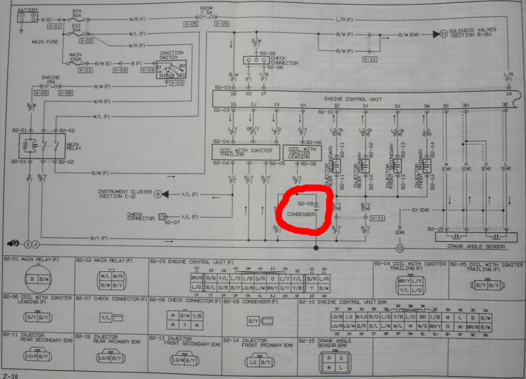
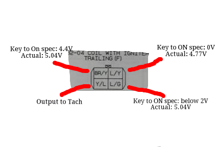
Blue/Yellow, pin 1G, should read 0 volts so you've got an issue there (and reads .8 volts while idling). Brown/Yellow, pin 1J. should read 4.4 volts w/key to on, and 2.2 when idled. Blue/Green, pin 1V, reads less than 2 volts key to on, and 1.4 volts idling.
And there is a condenser that is part of the wiring. Do you have it connected properly?
And there is a condenser that is part of the wiring. Do you have it connected properly?
Interesting. Unfortunately I have to quit the testing for today but I'll test all those wires tomorrow. I just looked through the wiring diagram and was beginning to see the voltages you just told me right before you responded, so I now know how to read a wiring diagram haha.
Sorry, I don't know what a condenser is.
Sorry, I don't know what a condenser is.
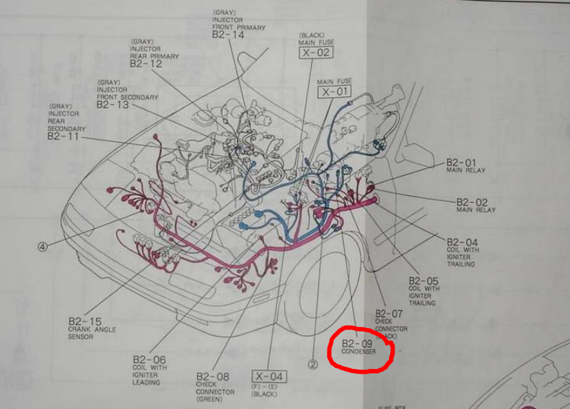
There are two condensers. One is for the tach and the other is for the oil gauge. They look like a computer chip connected to a wire. The chip looking part has a metal tongue w/a hole in it which is used to bolt the condenser to the body of the car. One is located on the slave cylinder (for the oil gauge) and I think the other is below the trailing coil. Sometimes the chip falls off and people ground the wire itself to the car which is wrong! See if this was done for the tach signal.
And you might want to test your coil readings at the ECU.
And you might want to test your coil readings at the ECU.
But I doubt those are the cause for your problems. Aren't the condensers just to reduce radio noise? Or does the interference go both ways (question to the experts)?
Wiring diagram shows the leading one circled. Other picture (of the car) points to condenser that mounts on the clutch slave cylinder. As said, there are two.
But I doubt those are the cause for your problems. Aren't the condensers just to reduce radio noise? Or does the interference go both ways (question to the experts)?
But I doubt those are the cause for your problems. Aren't the condensers just to reduce radio noise? Or does the interference go both ways (question to the experts)?
They are two independent items. The one you located near the trailing coil is the condenser intact or is it just a wire grounded to the body?
Yes the condenser is intact.
^That's good. And when you measure the pins at the ECU afterwards you can unplug the connector at the trailing coil and remeasure once again. When unplugged, one of the wires will revert to 12 volts which is normal.
Last edited by satch; Oct 9, 2014 at 04:05 PM.